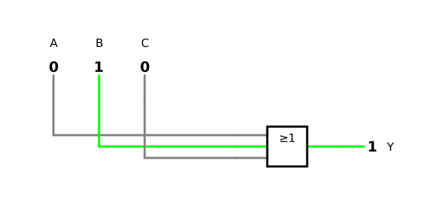
Many smartphones switch their screen on when you press the power button (A), when you lift the phone (B) or when a notification arrives (C); one of the three is enough. The output is Y, ‘screen on’. Subtask a) is based on an exercise in the textbook by LaMeres [5, p. 84].
a) Set up the truth table of Y.
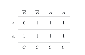
b) Draw the Karnaugh map of Y.
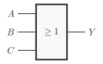
c) Draw the schematic symbol of the gate that forms Y, according to the standard of the International Electrotechnical Commission (IEC), IEC 60617.
the inputs A (‘power button pressed’), B (‘phone lifted’) and C (‘notification arrives’); one of the three is enough
the output Y, ‘screen on’
Known:
Truth table: all 2n combinations of the inputs in ascending order, like a binary count (DET-02); the OR gate (DET-02) and gates with more than two inputs (DET-02)
Karnaugh map with three inputs: two rows and four columns, with A marked on the left, B above and C below the grid (DET-02)
Schematic symbols according to the standard of the International Electrotechnical Commission (IEC), IEC 60617 (DET-02, DET-02)
Required
a) the truth table of Y
b) the Karnaugh map of Y
c) the schematic symbol of the gate that forms Y
a) Truth table
The screen is on as soon as at least one of the three inputs is 1. This is the OR operation with three inputs (DET-02, 3.4):
Y=A+B+C
With three inputs, the truth table has 23=8 rows, in ascending order like a binary count and numbered from row 0 to row 7 (DET-02, 2.2):
A
B
C
Y=A+B+C
0
0
0
0
0
0
1
1
0
1
0
1
0
1
1
1
1
0
0
1
1
0
1
1
1
1
0
1
1
1
1
1
Check with the rule of the OR gate: Y is 0 only in row 0, where none of the three events occurs ✓
b) Karnaugh map
With three inputs, the Karnaugh map has two rows and four columns. The labels at its edges show where each input is 1: A on the left, B above and C below the grid (DET-02, 2.6). Read from left to right, the columns stand for BC = 00, 01, 11, 10. Each output of the truth table goes into the cell with the number of its row: row 2 therefore goes into the fourth column and row 3 into the third, and the same holds for rows 6 and 7 in the lower row:
The map contains a single 0, at the top left in the cell of row 0; all other cells contain a 1.
Check by blocks: A=1 alone switches the screen on, so the whole row marked A contains 1s. The same holds for the two columns marked B above the grid and for the two columns marked C below it. Each input thus covers a block of four cells, and only the cell marked A, B and C lies outside all three blocks ✓
c) Schematic symbol
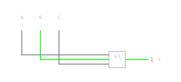
An OR gate with three inputs forms Y. According to IEC 60617, it is a rectangle with the qualifying symbol ≥1, which states the rule: at least one input is 1 (DET-02, 2.4, DET-02, 3.3). For three inputs, the rectangle simply gets a third input line (DET-02, 3.4):
Check with the rule of the qualifying symbol: ≥1 delivers a 0 only if none of the three inputs is 1, as in row 0 of the truth table ✓
In the simulation, you can check all three subtasks: switch the inputs through the eight combinations and compare Y with the truth table and the Karnaugh map. At the start, only B is 1, and Y already shows 1.