
Prof. Dr. Thorsten Jungmann (last updated 2026-10-20)
Relates to DET-03 Representation and minimization of logic functions
Task
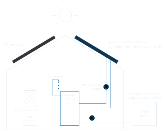
In our example system, an energy manager controls the heat pump through Smart Grid Ready (SG Ready). Its two switching signals and select one of four operating states: 0:0 is state 2, normal operation; 0:1 is state 3, boost; 1:0 is state 1, block; 1:1 is state 4, the start command. The energy manager selects state 3 when the photovoltaic (PV) system feeds surplus power into the grid; it never sends the start command, state 4. In states 1 and 2, the heat pump raises no set point. In state 3, it raises its set points for heating and for hot water, with two exceptions. In summer mode (German: Sommerbetrieb), the heating is off, and state 3 only raises the set point for hot water. While the solar thermal pump is running, the sun is already heating the hot water, and its set point is not raised. Besides and , the inputs and the outputs are:
- : summer mode is on
- : the solar thermal pump is running
- : the set point for hot water is raised
- : the set point for heating is raised
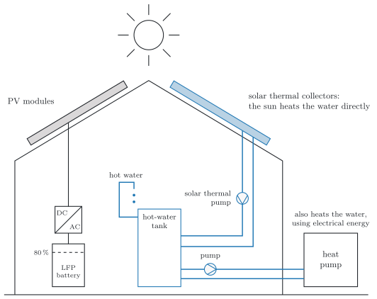
a) Set up the truth table of and . In the rows that never occur, mark the outputs as don’t cares.
b) Give and as minterm lists with don’t cares.
c) Minimize and with Karnaugh maps, using the don’t cares.
d) Describe the minimized circuit in VHDL.
e) What do your minimized circuits deliver if the energy manager sends the start command after all?
Solution
a) for , a 1 in rows 4 and 6; for , a 1 in rows 4 and 5; X in rows 12 to 15 for both; a 0 in all other rows
b) ;
c) and , each from a loop of four ones and don’t cares
d)Y <= B and not D;andZ <= B and not C;
e) for and , the circuits deliver for and for : they treat the start command like state 3