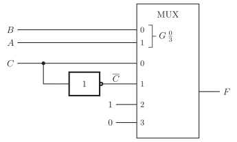
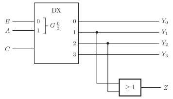
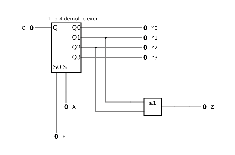
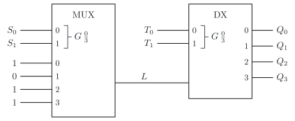
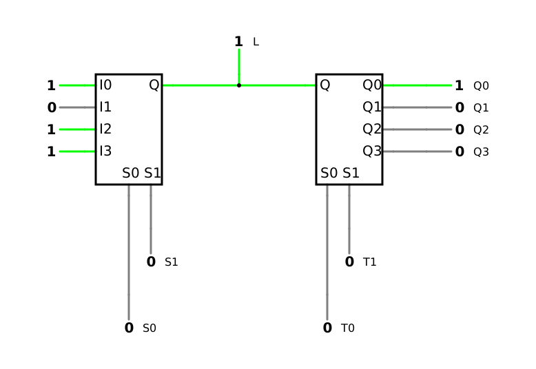
The three circuits below are drawn according to the standard of the International Electrotechnical Commission (IEC), IEC 60617. In each of them, follow the select inputs to find out what the multiplexers and demultiplexers do, and then fill in the gaps in the truth table. In the symbols, the data inputs and outputs carry their numbers; the data input with the number k is called Ik below.
Circuit 1 has the inputs A, B and C and the output F.
a) Fill in the gaps.
Row
A
B
C
Selected data input
F
0
0
0
0
I0
0
1
0
0
1
2
0
1
0
1
3
0
1
1
I1
4
1
0
0
5
1
0
1
I2
6
1
1
0
0
7
1
1
1
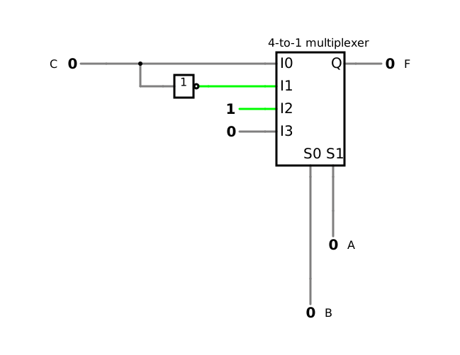
Check your truth table of a) in the simulation of circuit 1.
f) Under which condition does each output Qk show exactly its own data input Ik, and what happens otherwise? How would you have to drive the select inputs for all four signals to share the line L?
Solution
a) F is 1 in rows 1, 2, 4 and 5, 0 in all others
b) F(A,B,C)=∑m(1,2,4,5); F=A⋅B⋅C+A⋅B⋅C+A⋅B
c) Yk equals C for the k that A and B select, the other outputs are 0; Z is 1 in rows 3 and 5
d) Z=(A⊕B)⋅C; Z=1 if C=1 and A and B differ
e) L shows the data input that S1 and S0 select, Qk shows L for the k that T1 and T0 select, the other outputs are 0
f) only if both pairs of select inputs carry the number k; otherwise, the signal of the selected data input arrives at the output that T1 and T0 select, which then shows a foreign signal; for sharing, both pairs have to run through the numbers 0 to 3 together