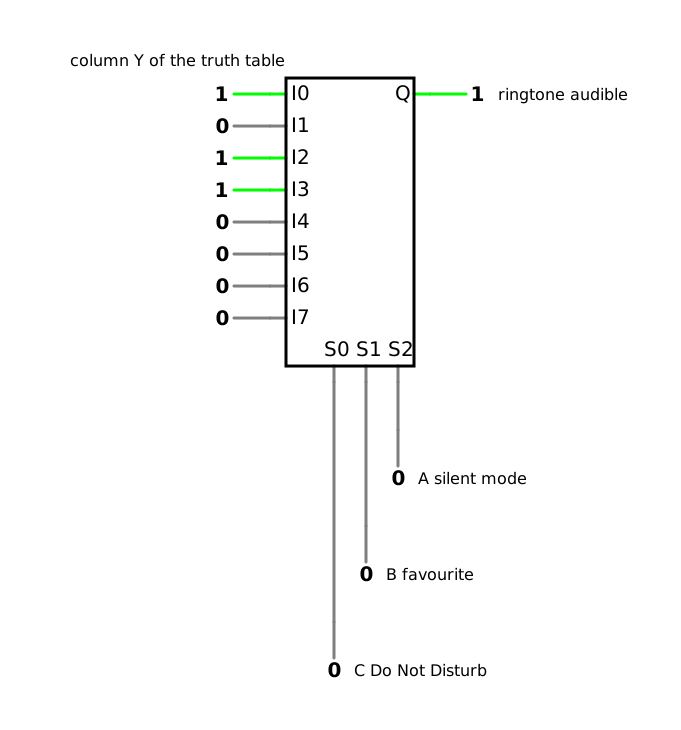
In the previous lesson, you minimized simple functions algorithmically, saw how the algorithm deals with functions with many inputs and found out why a correct circuit can still deliver a wrong value for a few nanoseconds.
An implicant implies the function; a prime implicant cannot be enlarged, and the essential prime implicants belong to every minimal disjunctive normal form (DNF).
The Quine–McCluskey algorithm finds all prime implicants table by table and selects them with the prime implicant chart.
Different delays cause hazards; a redundant prime implicant removes a logic hazard, a function hazard remains.
The output of a combinational logic circuit depends only on its present inputs; a sequential circuit also stores information.
Today, we look at how bits carry information as codes, and at standard components: combinational logic circuits that turn one code into another, select a signal or distribute it.
1 One character, many codes – Codes and coding
1.1 Code and code word
Barcode, QR code, Morse code – you meet codes every day, often without noticing. At the self-checkout of a supermarket, you hold each product in front of a scanner, which reads the bars of its barcode (photo). Morse code turns letters into short and long signals [12, p. 3], which you can send with a lamp or as a tone; a barcode puts characters into bars and spaces of different widths, which a scanner reads; a QR code arranges black and white squares in two dimensions, which the camera of your smartphone reads. Each of them is made for its medium.
In general terms, a code (German: Code) maps the characters of one set of characters onto the characters of a second set [12, p. 3]. A table defines the mapping, as for the Morse code [12, p. 3], and it should be reversible, so that the original character can be recovered from the coded one [12, p. 3]. For each application, some codes are better suited than others: arithmetic in a computer needs a different code from the transmission of numbers over a link [12, p. 3]. This is the short answer to the first guiding question; chapters 1 to 3 of this lesson show which code does which job.
In digital electronics, the second set of characters consists of 0 and 1. The bit pattern that a code assigns to a character is a code word (German: Codewort) [12, p. 13]. In DET-03, 4.4, and DET-04, 2.1, I called such bit patterns ‘codes’ for short, such as the code 0011 of minterm 3; strictly speaking, they are code words. Here, as in Fricke, all code words of a code have the same length [12, p. 3]. With n bits, there are 2n different code words. A code that uses all of them is a minimal code (German: Minimalcode); a code that uses fewer is a redundant code (German: redundanter Code) [12, p. 3]. A redundant code can pay off: chapter 2 of this lesson shows how additional bits make errors visible.
1.2 The binary code: power values and a code word for ‘not delivered’
The most important code in digital systems is the binary code (German: Dualcode) [12, p. 4]: it writes a number as the binary number that you know from DET-01, 6.3. Its bits have the weights of the powers of two, which makes it a weighted code (German: gewichteter Code) [12, p. 4], [9, p. 29]; with n bits, it uses all 2n code words and is a minimal code. Because the binary code allows an arithmetic like that of the decimal system, digital systems calculate with it [12, p. 4] (DET-01, chapter 8).
Our heat pump shows two more things that a code can carry. Example: the electrical power of the heat pump. The controller of our example system reports the electrical power that each heat pump draws as a whole number in units of 0.1 kW:
P=N⋅0.1kW
where:
P is the electrical power that the heat pump draws, in kilowatts (kW)
N is the whole number that the controller transmits in the binary code, without a unit
The number 47, for example, means P=47⋅0.1kW=4.7kW. The binary code transmits only the number; the unit 0.1 kW is part of the agreement between the controller and the device that reads the value. Whoever reads 47 as 47 kW is wrong by a factor of 10.
Second, the controller reserves one code word for a special meaning: the code word 800016 – in the documentation of our system written as 0x8000 – means ‘value not delivered’. Our system sends it, for example, for the temperatures of the heating circuits 2 and 3; it delivers them only for heating circuit 1. Read as a 16-bit number in two’s complement (DET-01, 9.3), 800016=10000000000000002 is −32 768, the smallest number that 16 bits can represent – far from any temperature or power that the heat pump could report.
1.3 Decimal digits in four bits: BCD code and excess-3 code
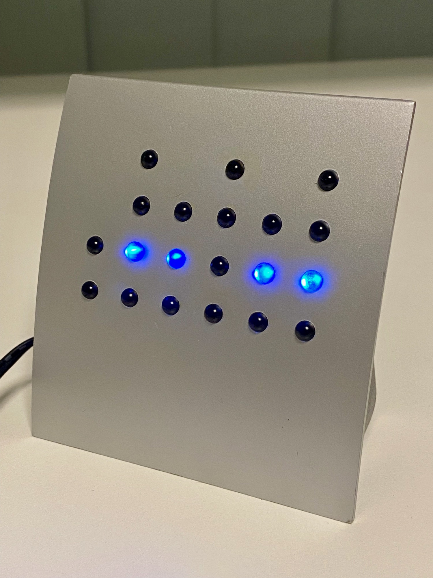
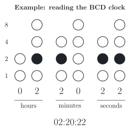
Example: a clock in the binary-coded decimal (BCD) code. From this lesson on, a third application example accompanies the smartphone and the heat pump: my BCD clock (photo). It shows the time with 20 blue light emitting diodes (LEDs) in six columns, for the tens and units of the hours, the minutes and the seconds. Each column shows one decimal digit in the BCD code (German: BCD-Code), which represents each decimal digit by a four-bit binary number [9, p. 29]. Its bits have the weights 8, 4, 2 and 1, which is why it is also called the 8421 code [9, p. 30], [12, p. 13]. On the clock, the weight 1 is at the bottom of each column, and the weights 2, 4 and 8 follow upwards (figure). The columns for the tens have only two or three LEDs, because the tens of the hours never exceed 2, and those of the minutes and seconds never exceed 5. Read the photo column by column and add the weights of the lit LEDs: 0, 2, 2, 0, 2 and 2 – the clock shows 02:20:22.
Of the 16 code words with four bits, BCD uses only ten, 0000 to 1001; the six code words 1010 to 1111 are invalid [9, pp. 29–30]. BCD is therefore a redundant code (section 1.1 of this lesson). Its advantage is the simple conversion: to write a decimal number in BCD, you replace each decimal digit by its four bits, and back [9, p. 31]. This is why BCD suits the decimal digits of a display [12, p. 13]. The price is more bits. Example: the message numbers of the heat pump. The controller of our heat pump records its messages under five-digit numbers, such as 30 008 and 50 004. In the binary code, 50 004 fits into 16 bits, 11000011010101002; in BCD, each of the five digits needs four bits, 20 bits in all: 0101 0000 0000 0000 0100.
A variant of BCD is the excess-3 code (German: Exzess-3-Code): each digit is represented by its value plus 3, that is, by its BCD code word plus 0011 [9, pp. 30–31], [21]. After Stibitz, it is also called the Stibitz code [21]. If you invert all bits of one of its code words, you get the code word of the nine’s complement (German: Neunerkomplement) of the digit, 9 minus the digit [9, pp. 30–31], [21]. The digit 2 is 0101; inverted, 1010 stands for 10 − 3 = 7, and indeed 9 − 2 = 7. This property made the arithmetic of decimal digits simpler in hardware [9, pp. 30–31], for example in cash registers and pocket calculators of the 1970s [21].
Digit
BCD code
Excess-3 code
0
0000
0011
1
0001
0100
2
0010
0101
3
0011
0110
4
0100
0111
5
0101
1000
6
0110
1001
7
0111
1010
8
1000
1011
9
1001
1100
1.4 One bit at a time: the Gray code
In DET-04, 4.4, a counter went from 3 to 4, from 011 to 100: all three bits changed, and because they never change at exactly the same moment, an AND gate saw 111 or 110 for a moment. The same happens when a position is read in the binary code. Fricke shows it with the change from 1 to 2, from 0001 to 0010: if bit 0 changes first, 0000 appears for a moment; if bit 1 changes first, 0011 [12, pp. 12–13].
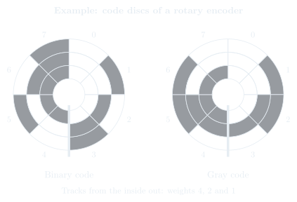
The Gray code (German: Gray-Code) avoids such errors: from one code word to the next, only one bit changes [12, p. 13], [22]. Lou and Yang call such a code a unit-distance code (German: einschrittiger Code) [9, p. 31]. The three-bit Gray code in the table is also cyclic: from 7 back to 0, only one bit changes as well [12, p. 13]. Unlike the binary code, the Gray code is not weighted and is not used for arithmetic [9, p. 31].
Decimal
Binary code
Gray code
0
000
000
1
001
001
2
010
011
3
011
010
4
100
110
5
101
111
6
110
101
7
111
100
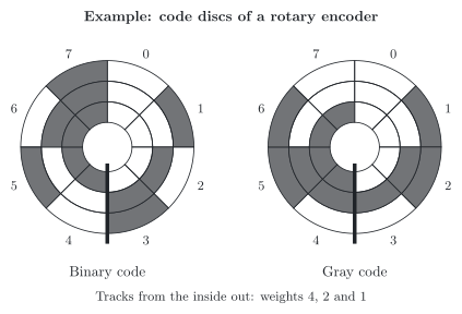
Example: rotary encoders. A rotary encoder (German: Drehgeber) reads the position of a shaft, for example on the volume knob of a car radio, at the joints of a robot arm or on machine tools. On its code disc, each position carries a code word in several tracks (figure). With the binary code, a reading at the border between two positions can catch some bits before and others after the change; with the Gray code, only one bit changes there, so that a misread is off by one position at most [22].
You know the Gray code already: the labels of the Karnaugh map in DET-03, 4.1, follow it. Its columns run through 00, 01, 11 and 10, so that neighbouring cells differ in exactly one input; Karnaugh maps have used the Gray code for labelling their axes since 1953 [22].
Frank Gray
In his patent application of 1947, the Bell Labs researcher Gray called the code the ‘reflected binary code’; the patent was granted in 1953 [22]. The principle is older: Stibitz described such a code in a patent application of 1941 [22].
1.5 Letters and digits: ASCII and Code 39
A code for texts is an alphanumeric code (German: alphanumerischer Code): it represents letters, digits, punctuation marks and control characters [9, p. 32]. The most common one is the American Standard Code for Information Interchange (ASCII), which codes 128 characters with seven bits [9, p. 32]. The letter A, for example, has the code word 4116=10000012, the digit 0 the code word 3016 (table) [12, p. 14].
Character
ASCII, hexadecimal
ASCII, binary
space
20
010 0000
0
30
011 0000
9
39
011 1001
A
41
100 0001
B
42
100 0010
a
61
110 0001
Example: a text on your smartphone. When you type the letter A on your smartphone, it becomes a code word, for example in UTF-8, the code in which almost every web page is transmitted today [23]. UTF-8 was designed to be compatible with ASCII: its first 128 characters have the same code words as in ASCII, each in a single byte [23]. In industry, machines exchange texts as well: the Modbus protocol has an ASCII variant, in which controllers send their data as readable characters, and machine tools receive their instructions as text in G-code.
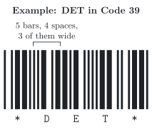
A barcode codes characters for a scanner. Code 39 (German: Code 39), developed in 1974, codes 43 characters: the digits 0 to 9, the capital letters A to Z and some special characters, including the space [24]. Each character consists of nine elements, five bars and four spaces; three of them are wide, the other six narrow [24]. An additional character, the asterisk, marks the start and the end (figure) [24]. Because exactly three of the nine elements are wide, a single misread bar cannot produce another valid character, so the code detects such an error by itself [24] – a first glimpse of chapter 2 of this lesson. Example: medicine packages. In Germany, the Pharmazentralnummer (PZN), the pharmaceutical central number of a medicine, stands on its package as a barcode in Code 39 [25]. In the automotive industry, the goods tags on containers and pallets of the supply chain follow recommendation 4902 of the German Association of the Automotive Industry (VDA) and carry Code 39 as well. The barcode on food in the supermarket, in contrast, is not a Code 39 but an EAN-13, which knows only digits.
2 When a bit flips – Error-detecting and error-correcting codes
2.1 Parity bit and Hamming distance
When data are sent or stored, electromagnetic interference can flip single bits. If the flipped bit turns one valid code word into another, nobody notices. Example: the digit 7 in the binary-coded decimal (BCD) code. Beuth and Beuth show it with the digit 7, which is 0111 in BCD: if one of its ones turns into a 0 on the way, the receiver may get 0101 – a valid code word, the digit 5, and nothing reveals the error [15, pp. 277–278]. An error can only be detected if more information is transmitted than is strictly needed; this additional information is called redundancy (German: Redundanz) [15, pp. 277–278], from the Latin redundans, overflowing [15, p. 277].
The simplest redundancy is one additional bit, the parity bit (German: Paritätsbit). With even parity (German: gerade Parität), it completes each code word so that the number of its ones is even [15, pp. 278–279]. For 0111, which has three ones, the parity bit is 1: 0111 1. The receiver counts the ones again; if their number is odd, a bit has flipped [15, p. 279]. Counting ones is a job that you know: the XOR operation delivers a 1 for an odd number of ones (DET-03, 4.5), so a chain of XOR gates computes the parity bit. A parity bit detects one flipped bit, but cannot tell which one, and two flipped bits go unnoticed, because the number of ones is even again [15, p. 279]. A code with such redundancy is an error-detecting code (German: fehlererkennender Code) [15, p. 277].
How far apart are two code words? The Hamming distance (German: Hamming-Abstand) between two code words of the same length is the number of positions in which they differ [26]. 0111 and 0101 have the distance 1. In DET-04, 2.1, the Quine–McCluskey algorithm united terms whose codes differ in exactly one position: code words with the Hamming distance 1. The smallest distance between any two code words of a code decides how many flipped bits it detects or corrects with certainty: with a smallest distance of two, it detects every single flipped bit; with three, it detects every error of up to two flipped bits or corrects every single one [26]:
Smallest distance between two code words
Detected with certainty
Corrected with certainty
Example
1
none
none
BCD code
2
1 flipped bit
none
BCD code with parity bit
3
2 flipped bits
1 flipped bit
the code of section 2.2 of this lesson
The BCD code has the smallest distance 1, because 0111 and 0101 are both valid code words. Its six unused code words reveal only some flipped bits: if the bit with the weight 2 of 1001 flips, the receiver gets the invalid 1011, whereas 0111 became the valid 0101.
2.2 The Hamming code
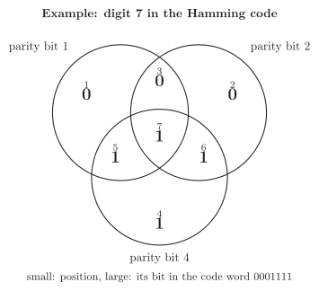
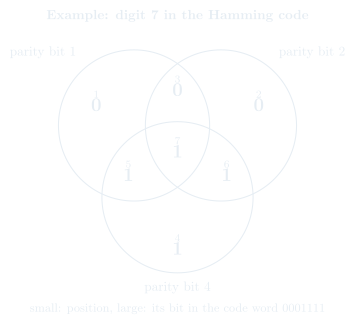
With three parity bits, a code can do more than detect an error: it can find the flipped bit and correct it. The Hamming code (German: Hamming-Code) in its form with seven bits adds three parity bits to four data bits [15, p. 283], [27]; longer forms exist for more data bits [27]. The bits are numbered from 1 to 7; the parity bits stand at the positions 1, 2 and 4, the data bits at 3, 5, 6 and 7 [27]. Each parity bit covers three data bits and completes them to an even number of ones: the parity bit at position 1 covers the positions 3, 5 and 7, the one at position 2 covers 3, 6 and 7, and the one at position 4 covers 5, 6 and 7 [15, pp. 283–284], [27] (figure).
The receiver counts the ones of each parity bit together with its three data bits again. Each of these three sets of positions with an odd number of ones points to the error, and the positions of their parity bits add up to the position of the flipped bit [27], [15, p. 286]. The receiver inverts this bit, and the code word is correct again [15, p. 286]. Example: the digit 7 in the Hamming code. With the data bits 0, 1, 1 and 1 of the digit 7 at the positions 3, 5, 6 and 7, the code word is 0001111 (table). If the bit at position 6 flips on the way, the receiver gets 0001101: the sets of the parity bits at the positions 2 and 4 now have an odd number of ones, and 2 + 4 = 6. The receiver inverts bit 6 and has the digit 7 back, where BCD alone would have delivered a 5 (section 2.1 of this lesson).
Position
1
2
3
4
5
6
7
Bit
parity bit
parity bit
data bit
parity bit
data bit
data bit
data bit
Covered by the parity bits at
1
2
1 and 2
4
1 and 4
2 and 4
1, 2 and 4
Example: digit 7
0
0
0
1
1
1
1
Any two code words of this code differ in at least three positions; by the table in section 2.1 of this lesson, it corrects one flipped bit or detects two [27]. A code that finds and corrects errors by itself is an error-correcting code (German: fehlerkorrigierender Code) [15, p. 282].
Example: your Bluetooth headphones. Bluetooth, which connects your smartphone with wireless headphones, protects the data of certain packets with a shortened Hamming code: it adds five parity bits to every ten data bits and corrects every single flipped bit in each block of 15 bits [28]. In industry, memory with an error-correcting code (ECC memory) in industrial computers, servers and controllers uses an extended Hamming code: it corrects a single flipped bit when the memory is read and detects two [27].
Richard Hamming
At Bell Labs, Hamming was frustrated that errors forced him to restart his programs on the computer Bell Model V; in the late 1940s, he developed the codes that bear his name, and he published them in 1950 [27].
3 One output for each code word – Decoders
3.1 The decoder and the one-hot code
Some jobs come up in almost every digital system: picking out one code word, turning one code into another, selecting one of several signals. For such jobs, there are standard components (German: Standardbausteine) [12, p. 111]: combinational logic circuits (DET-04, 5.1) for jobs that occur again and again, available as integrated circuits (DET-02, 1.1) [15, p. 293]. LaMeres calls them medium-scale integrated circuit (MSI) logic, and each of them can be designed with the steps of combinational logic design [5, p. 191]. From this chapter on, I design the standard components and code converters of this lesson with the six steps of the synthesis from DET-03, 1.1, and name each step where we take it.
A code converter (German: Codewandler) turns information that is represented in one code into another code [15, p. 291], [12, p. 114]. The first code converter of this lesson is the decoder (German: Decoder): it takes in a code word and has outputs that are 1 for specific code words [5, p. 191]. A decoder with n inputs and 2n outputs sets exactly one output to 1 for each code word: its outputs form the one-hot code (German: 1-aus-n-Code), in which exactly one bit is 1 [5, p. 191]. In programmable devices, the states of sequential circuits are often stored in the one-hot code, because a single 1 is quick to recognize.
Steps 1 and 2 of the synthesis for a 2-to-4 decoder: inputs A and B, A with the weight 2, and outputs Y0 to Y3, where Yi is 1 for the code word with the number i (table) [5, p. 192].
A
B
Y0
Y1
Y2
Y3
0
0
1
0
0
0
0
1
0
1
0
0
1
0
0
0
1
0
1
1
0
0
0
1
Steps 3 and 4: each output has a single one, so its canonical disjunctive normal form (DNF) is one minterm, which cannot be minimized [5, p. 192]:
Y0=A⋅BY1=A⋅BY2=A⋅BY3=A⋅B
where:
A and B are the inputs, each 0 or 1, A with the weight 2
Y0 to Y3 are the outputs, each 0 or 1
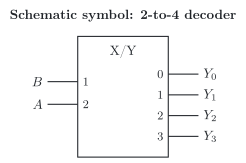
Read: Y0 is 1 only if A and B are both 0, Y3 only if both are 1. Step 5: four AND gates and two inverters, whose outputs A and B the AND gates share [5, p. 192]. In the schematic symbol according to the standard of the International Electrotechnical Commission (IEC), IEC 60617, the upper edge of the rectangle names the input code and the output code [12, p. 114], for example BIN/OCT for a decoder from the binary code to one of eight outputs [9, p. 112]. If the inputs are labelled with their weights and the outputs with the numbers of the code words for which they become 1, the general qualifying symbol X/Y remains [30], as for the 2-to-4 decoder (figure).
3.2 SG Ready with a lockout
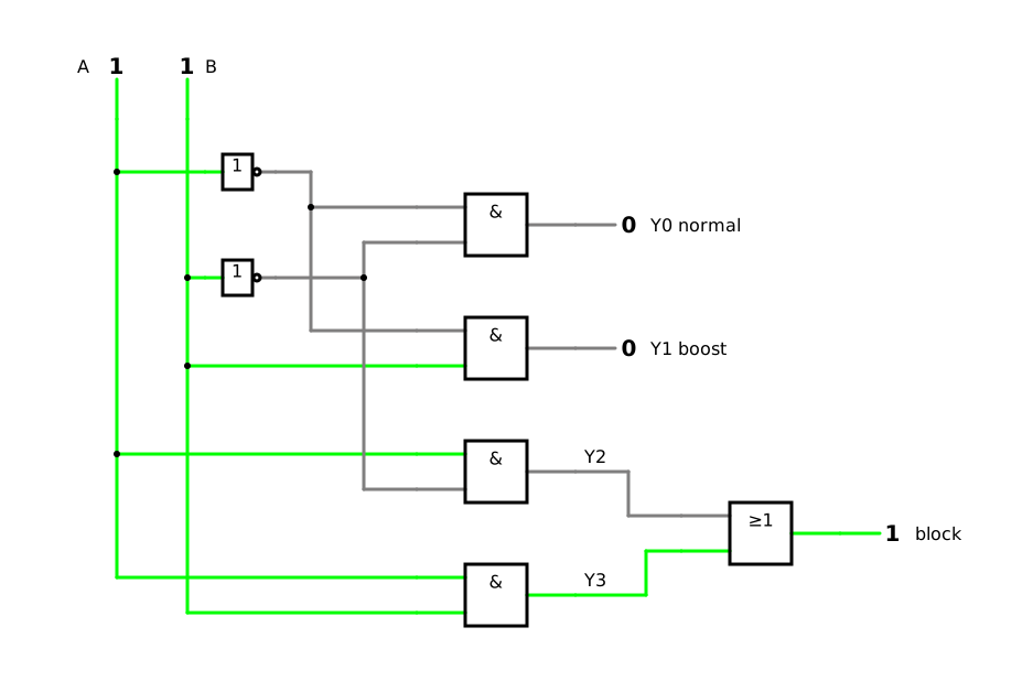
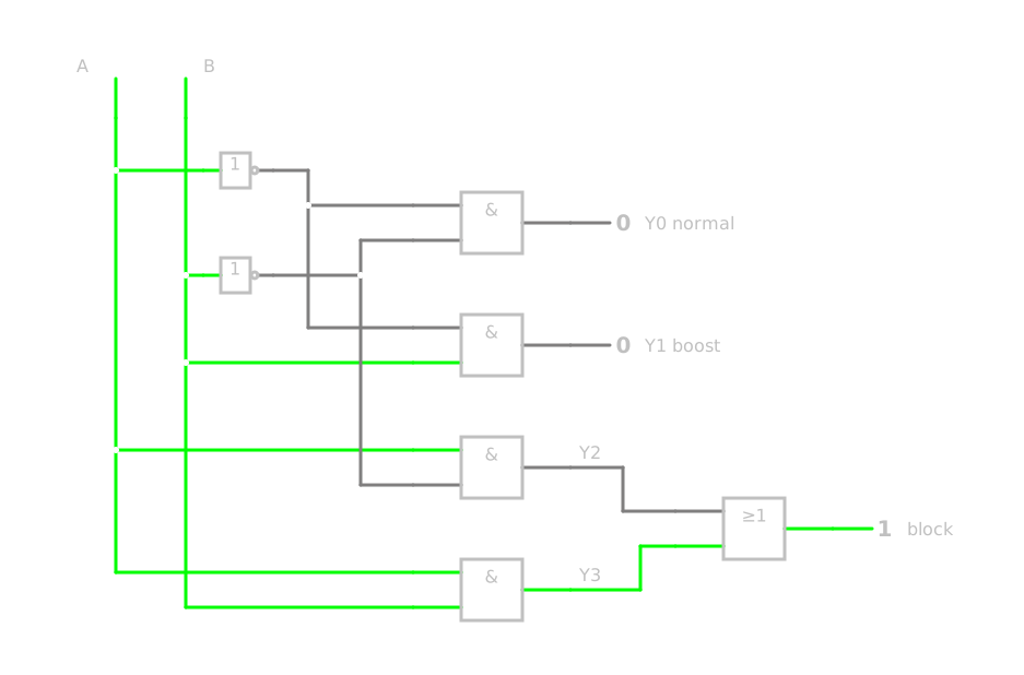
Example: Smart Grid Ready (SG Ready) with a lockout. You know the 2-to-4 decoder from DET-02, 6.6: the four gates that turn the two switching signals A and B of SG Ready into the four operating states. There, I numbered the outputs by the operating states; the decoder numbers them by the code words: Y0 (0:0) is normal operation, Y1 (0:1) boost, Y2 (1:0) block and Y3 (1:1) the start command [13]. In our example system, the start command must never act; the automation of the energy manager therefore never switches both signals on at once. For a lockout (German: Verriegelung) of the start command that also holds if 1:1 arrives by mistake, an OR gate leads Y3 into the block (simulation):
Yblock=Y2+Y3=A⋅B+A⋅B=A
where:
Yblock is the output ‘block’ of the locked decoder, 0 or 1
A and B are the two switching signals of SG Ready, each 0 or 1
Y2 and Y3 are the outputs of the decoder for the code words 1:0 and 1:1
The last equality is the uniting theorem (DET-03, 3.2). Read: the heat pump is blocked whenever the first switching signal A is 1, whatever B says; normal operation and boost remain Y0 and Y1. The block of the energy supplier thus has priority over the boost, and the start command never occurs. A don’t care for 1:1, as in DET-03, 4.4, would leave the reaction to the minimization; the lockout gives the combination 1:1 a defined, safe reaction.
A decoder can also point to something. Example: the flipped bit in the Bluetooth receiver of your smartphone. For the Hamming code with seven bits of section 2.2 of this lesson, a 3-to-8 decoder could point to the flipped bit: its three inputs, with the weights 1, 2 and 4, receive a 1 where the set of the parity bit at the position 1, 2 or 4 has an odd number of ones; the decoder then sets exactly the output with the number of the flipped bit to 1, and its output 0 means ‘no error’. For the longer code words of Bluetooth, such a decoder needs more inputs. Section 4.3 of this lesson builds the circuits that deliver these inputs.
3.3 The 7-segment display and its code
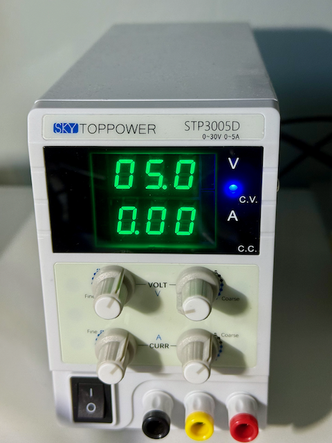
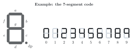
Example: the display of a laboratory power supply. The laboratory power supply in the photo shows the voltage and the current that you set, here 5.0 V and 0.00 A, with 7-segment displays. A 7-segment display (German: 7-Segment-Anzeige) forms each digit from seven light emitting diodes (LEDs), the segments a to g, often with a decimal point (figure) [5, p. 194], [9, p. 112]. Which segments form which digit is fixed by the 7-segment code (German: 7-Segment-Code): the digit 3, for example, needs the segments a, b, c, d and g, the 8 all seven [15, p. 301]. 7-segment displays are found in digital clocks and household appliances [5, p. 194] and, in industry, in displays of measured values and in the floor indicators of lifts.
The clock of section 1.3 of this lesson shows the same digits in a different way (table): it lights the code word of each digit in the binary-coded decimal (BCD) code itself, and whoever reads it adds the weights; the 7-segment display shows the shape of the digit, which you read at a glance. For this, it needs a code converter that turns the BCD code word into the seven segment signals: the 7-segment display decoder (German: 7-Segment-Decoder) [5, p. 194], [15, p. 303].
BCD clock
7-segment display
Light sources per digit
up to four LEDs with the weights 8, 4, 2 and 1
seven segments a to g
What lights up
the BCD code word
the shape of the digit
Reading
add the weights of the lit LEDs
read the digit at a glance
Code converter
none
7-segment display decoder
Example
the clock in section 1.3
the laboratory power supply
Step 1 of the synthesis: four inputs A, B, C and D for the BCD code word, A with the weight 8, and seven outputs Ya to Yg, each 1 when its segment lights up [5, p. 195]. Step 2: the truth table. The code words 1010 to 1111 never occur in BCD (section 1.3 of this lesson); their outputs do not matter and become don’t cares, marked X, as in DET-03, 4.4 [15, p. 303]. The digits 0 to 7 follow LaMeres [5, p. 195], the 8 lights all segments, and the 9, as in the 7-segment display decoder of the simulator, has no segment d.
Digit
A
B
C
D
Ya
Yb
Yc
Yd
Ye
Yf
Yg
0
0
0
0
0
1
1
1
1
1
1
0
1
0
0
0
1
0
1
1
0
0
0
0
2
0
0
1
0
1
1
0
1
1
0
1
3
0
0
1
1
1
1
1
1
0
0
1
4
0
1
0
0
0
1
1
0
0
1
1
5
0
1
0
1
1
0
1
1
0
1
1
6
0
1
1
0
1
0
1
1
1
1
1
7
0
1
1
1
1
1
1
0
0
0
0
8
1
0
0
0
1
1
1
1
1
1
1
9
1
0
0
1
1
1
1
0
0
1
1
–
1
0
1
0
X
X
X
X
X
X
X
–
1
0
1
1
X
X
X
X
X
X
X
–
1
1
0
0
X
X
X
X
X
X
X
–
1
1
0
1
X
X
X
X
X
X
X
–
1
1
1
0
X
X
X
X
X
X
X
–
1
1
1
1
X
X
X
X
X
X
X
3.4 Minimizing the segments with don’t cares
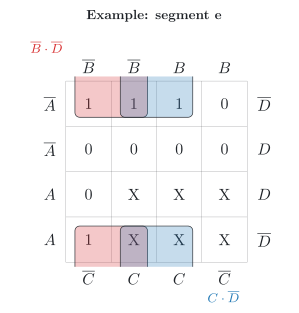
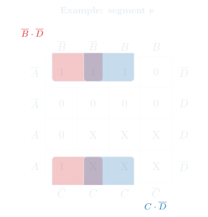
Steps 3 and 4: each of the seven outputs needs its own minimized expression, from its own Karnaugh map [5, p. 195], [15, p. 303]. Example: segment e. Segment e lights up for the digits 0, 2, 6 and 8. In its map (figure), the X in the cells 10 to 15 may be treated as ones where they enlarge loops (DET-03, 4.4) [15, p. 303]. Two loops of four cover the four ones, both across the upper and the lower edge of the map: B⋅D with the cells 0, 2, 8 and 10, and C⋅D with the cells 2, 6, 10 and 14:
Ye=B⋅D+C⋅D
where:
Ye is the output for segment e, 0 or 1
A, B, C and D are the bits of the BCD code word, each 0 or 1, A with the weight 8
Read: segment e lights up for an even digit, with D = 0, if B = 0 or C = 1. Without the don’t cares, that is, with a 0 in the cells 10 to 15, the minimal DNF would need two product terms with three literals each, B⋅C⋅D+A⋅C⋅D.
The other segments follow in the same way (table). Several product terms appear in more than one segment, for example B⋅D in a, d and e and C⋅D in d, e and g. A decoder can share such terms between its outputs, so that each shared term needs only one AND gate [5, pp. 198, 533]. For segment g, there are two minimal DNFs of the same size, as in DET-04, 1.3: with C⋅D or with B⋅D; the table chooses C⋅D, which d and e use as well.
Segment
Minimal DNF
a
Ya=A+C+B⋅D+B⋅D
b
Yb=B+C⋅D+C⋅D
c
Yc=B+C+D
d
Yd=B⋅D+B⋅C+C⋅D+B⋅C⋅D
e
Ye=B⋅D+C⋅D
f
Yf=A+C⋅D+B⋅C+B⋅D
g
Yg=A+B⋅C+B⋅C+C⋅D
The 7-segment display decoder of the simulator, which you met in DET-01, 3.5, uses the six unused code words in its own way: it shows the hexadecimal digits A to F for them.
3.5 The 7-segment display decoder as circuit and VHDL code
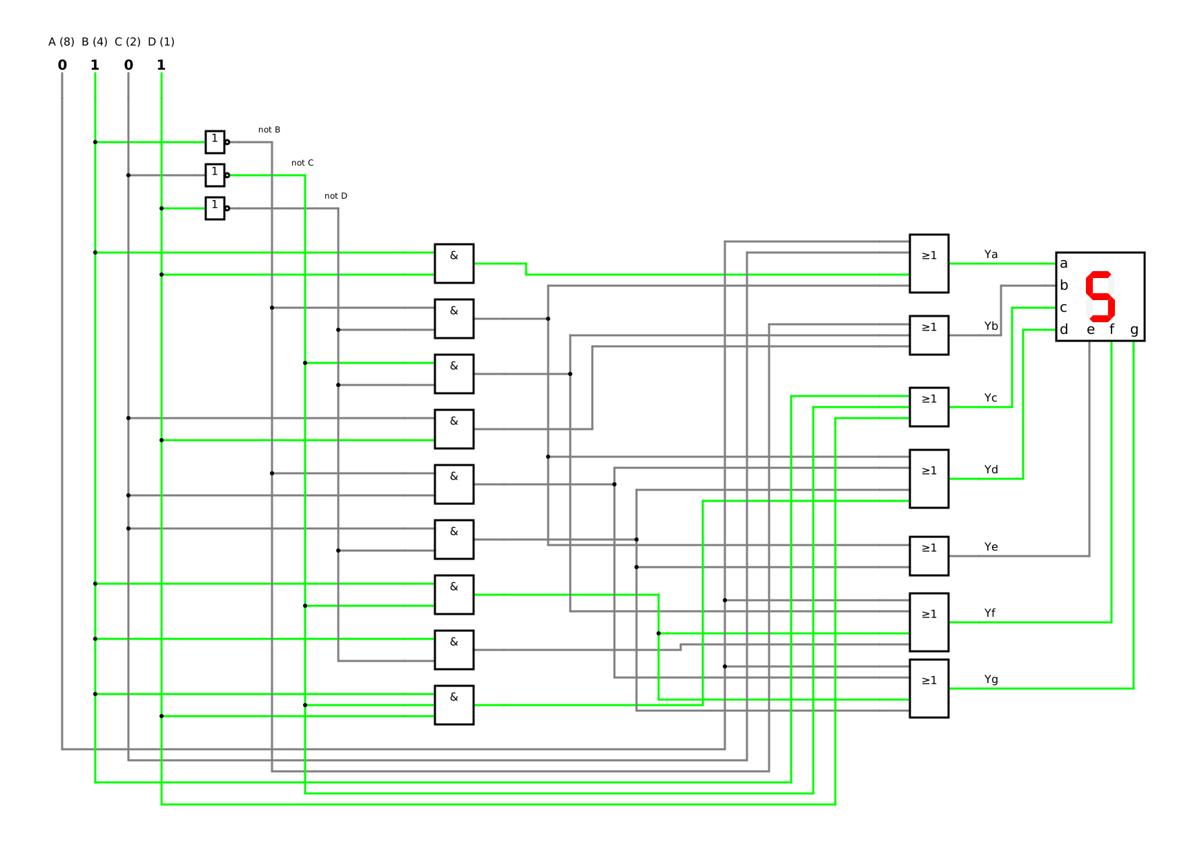
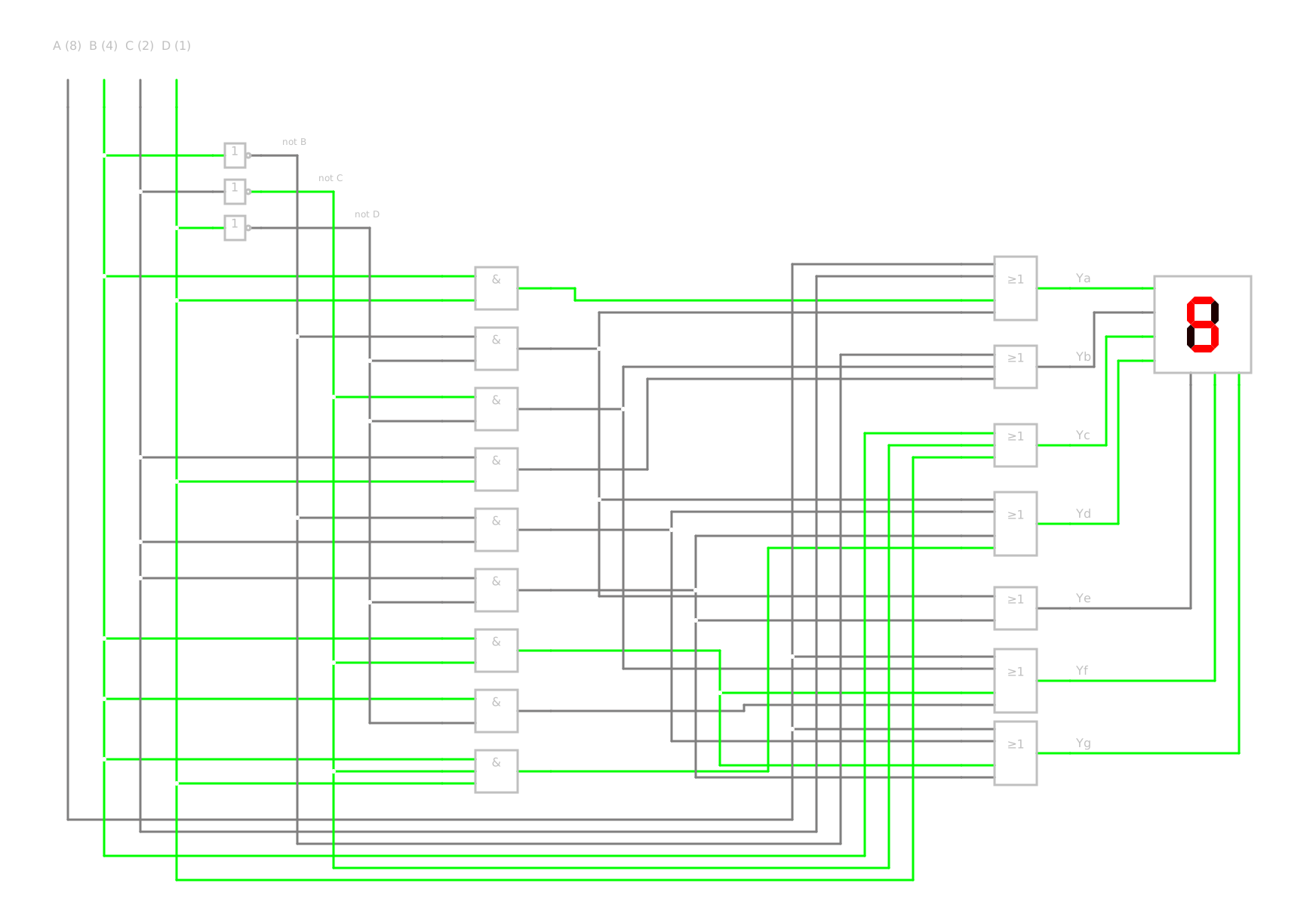
Step 5: the circuit follows from the seven expressions of section 3.4 of this lesson, with the shared AND gates and one OR gate for each segment (simulation). Step 6: in the simulator, switch the four inputs through the ten code words 0000 to 1001 and compare each digit on the 7-segment display with the truth table of section 3.3 of this lesson.
Step 5 also works as VHDL code. With a selected signal assignment (German: Auswahlzuweisung), LaMeres describes a 7-segment display decoder directly from its truth table [5, p. 198]: the keyword with … select assigns a segment pattern to each code word. Here, the code words 1010 to 1111 get the pattern 0000000, a dark 7-segment display; in VHDL, when others names the value for all code words that are not listed [5, p. 199]:
-- BCD: code word ABCD of a decimal digit, A with the weight 8-- Y: segments a to g, from Y(6) for a to Y(0) for gentity seven_segment is port (BCD : in bit_vector(3 downto 0); Y : out bit_vector(6 downto 0));end entity;architecture behaviour of seven_segment isbegin with BCD select Y <= "1111110" when "0000", -- 0 "0110000" when "0001", -- 1 "1101101" when "0010", -- 2 "1111001" when "0011", -- 3 "0110011" when "0100", -- 4 "1011011" when "0101", -- 5 "1011111" when "0110", -- 6 "1110000" when "0111", -- 7 "1111111" when "1000", -- 8 "1110011" when "1001", -- 9 "0000000" when others; -- 1010 to 1111: darkend architecture;
Read: for the code word 0000, the outputs a to g become 1111110, the digit 0. You do not minimize anything yourself: the synthesis tool (DET-04, 3.3) does that while it turns the VHDL code into a circuit.
4 From one code to another – Encoders and code converters
4.1 The encoder
An encoder (German: Encoder) works the other way round from a decoder: a 1 at one specific input produces a unique code word at its outputs [5, p. 199]. An encoder with 2n inputs and n outputs turns the one-hot code back into the binary code [5, p. 199].
Steps 1 and 2 for a 4-to-2 encoder: inputs I0 to I3, of which exactly one is 1, and outputs Y1 and Y0, which give the number of this input as a binary number (table) [5, p. 199]. All other combinations of the inputs are not specified, and LaMeres treats their outputs as don’t cares [5, p. 199].
I3
I2
I1
I0
Y1
Y0
0
0
0
1
0
0
0
0
1
0
0
1
0
1
0
0
1
0
1
0
0
0
1
1
Steps 3 and 4: in the map of each output, the don’t cares allow the largest loops [5, p. 199]:
Y1=I2+I3Y0=I1+I3
where:
I0 to I3 are the inputs, each 0 or 1, of which exactly one is 1
Y1 and Y0 are the outputs, each 0 or 1, Y1 with the weight 2
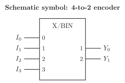
Read: Y1 is 1 if I2 or I3 is 1, Y0 if I1 or I3 is 1. Step 5: two OR gates; the input I0 is not even needed, because its code word is 00 [5, p. 199]. If the outputs must be 0 for all combinations that are not specified, these combinations are no longer don’t cares but zeros [5, pp. 201, 533]. And if two inputs are 1 at once? The two OR gates then deliver the OR of the two code words, for example 11 for the inputs I1 and I2 – the code word of I3. A priority encoder (German: Prioritätsencoder) avoids this: it encodes only the active input with the highest priority [9, p. 101]. In the schematic symbol, the inputs carry the numbers 0 to 3, and the qualifying symbol X/BIN names the binary code at the outputs, which carry the weights 1 and 2 [30] (figure).
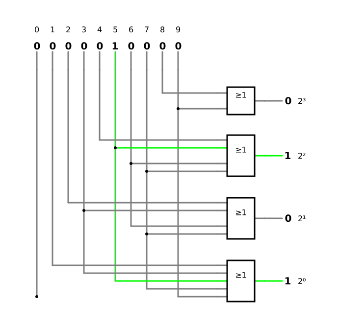
Example: a keypad with the digits 0 to 9. A keypad with ten keys delivers the decimal code, a one-hot code with one electric line per key. An encoder from the decimal code into the binary-coded decimal (BCD) code needs four OR gates, one for each weight, and the key 0 needs no gate at all, because its code word is 0000 [15, p. 293]. In my simulation, the output with the weight 8 combines the keys 8 and 9, the weight 4 the keys 4 to 7, the weight 2 the keys 2, 3, 6 and 7, and the weight 1 the odd digits.
Encoders and decoders form a pair. Example: the keyboard of your smartphone. It does the job of an encoder, in software: the key that you touch becomes its code word, for example the code word of a letter in the American Standard Code for Information Interchange (ASCII) (section 1.5 of this lesson) [9, p. 32]. Example: the energy manager at the heat pump. An energy manager could encode the operating state that it wants into the two signals of Smart Grid Ready (SG Ready): block, normal operation or boost become the code words 1:0, 0:0 and 0:1. As long as it wants exactly one of these three states at a time, it never sends 1:1, the start command – a lockout already at the transmitter, while the decoder of section 3.2 of this lesson provides the lockout at the receiver.
4.2 From binary code to Gray code and back
Example: the rotary encoder of a robot arm. The rotary encoder at a joint of a robot arm delivers its position in the Gray code (section 1.4 of this lesson), while the controller calculates in the binary code. The controller therefore needs a code converter from the Gray code into the binary code. We design the opposite direction first, from binary to Gray, because the code table of section 1.4 of this lesson lists the Gray code words in the order of the binary numbers.
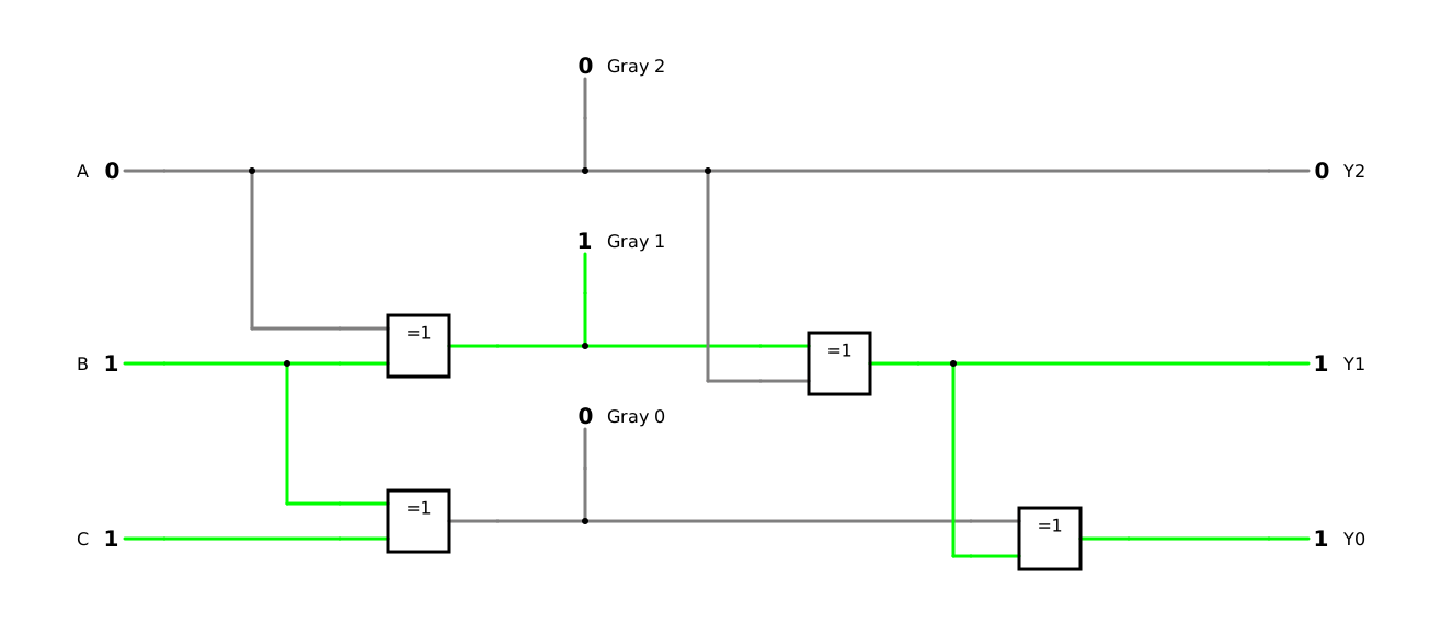
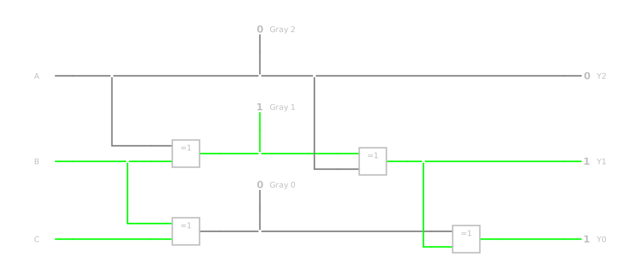
Steps 1 and 2: inputs A, B and C for a binary code word, A with the weight 4, and outputs Y2, Y1 and Y0 for the Gray code word, with the truth table of section 1.4 of this lesson. Steps 3 and 4: Y2 equals A. Y1 is 1 exactly where A and B differ, and Y0 where B and C differ – the XOR operation of DET-02, 4.3:
Y2=AY1=A⊕BY0=B⊕C
where:
A, B and C are the bits of the binary code word, each 0 or 1, A with the weight 4
Y2, Y1 and Y0 are the bits of the Gray code word, each 0 or 1
In words: each bit of the Gray code word is the bit of the binary code word, inverted if the next higher binary bit is 1 [22]. Step 5: two XOR gates.
The way back needs a chain. Now A, B and C are the bits of a Gray code word, and each bit of the binary code word is the XOR of the Gray bit at its position and the binary bit above it [22]:
Y2=AY1=A⊕BY0=Y1⊕C
where:
A, B and C are the bits of the Gray code word, each 0 or 1
Y2, Y1 and Y0 are the bits of the binary code word, each 0 or 1, Y2 with the weight 4
Because Y0 needs Y1, the two XOR gates stand one behind the other, from the highest bit down. Step 6 (simulation): connect both code converters one behind the other, from binary to Gray and back; for all eight code words, the outputs must equal the inputs.
4.3 The parity bits of the Hamming code as a circuit
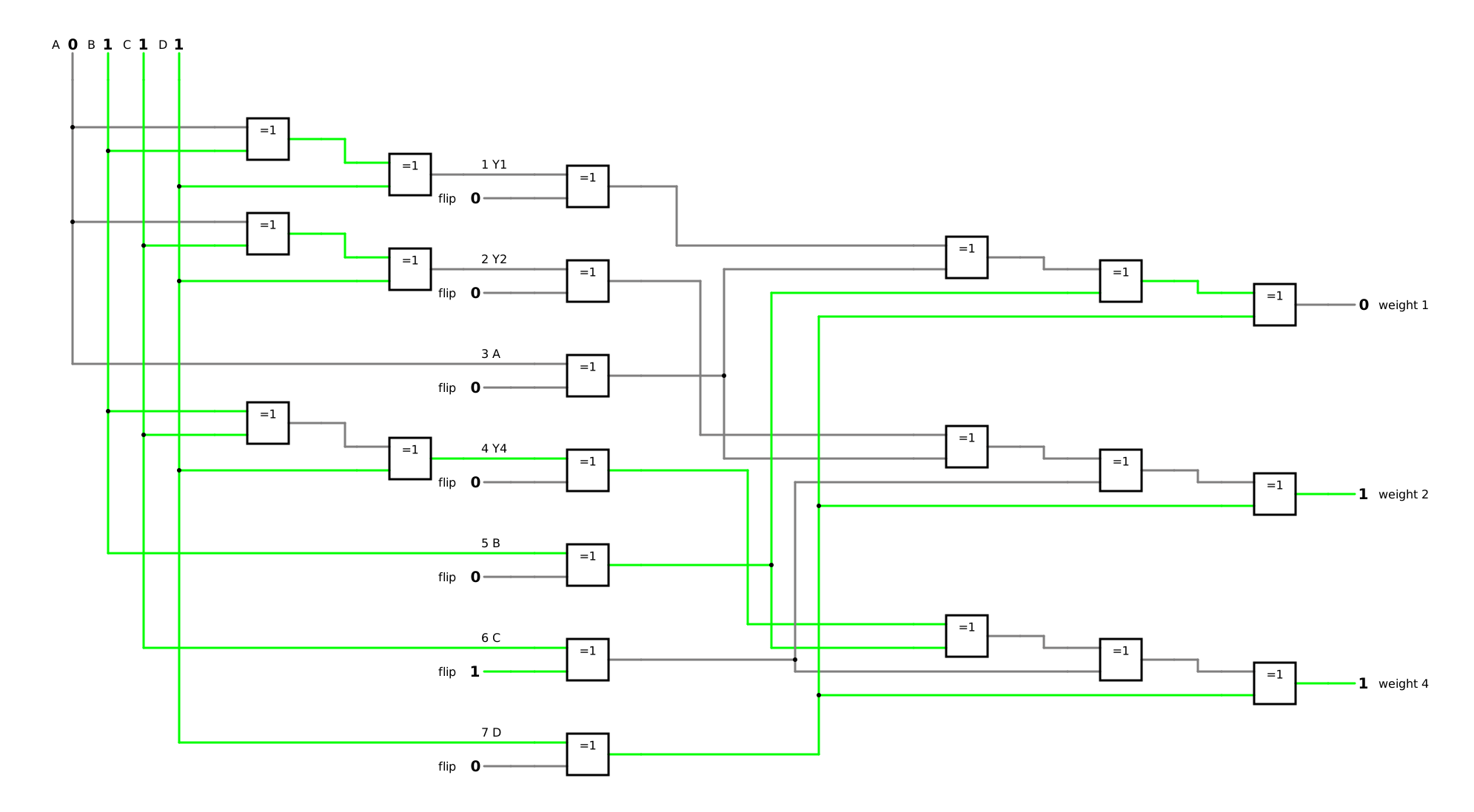
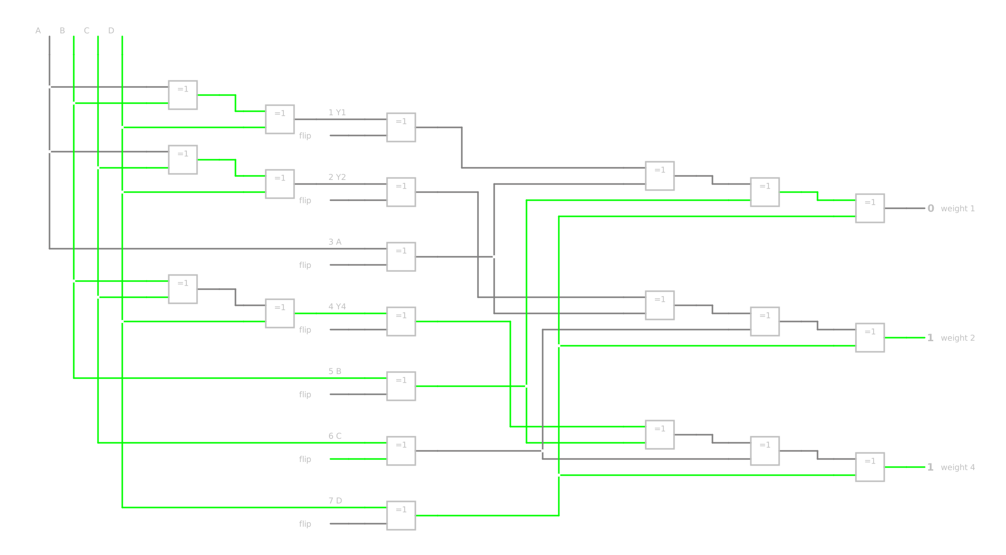
Example: the parity bits for the digit 7 in the Hamming code (section 2.2 of this lesson). Steps 1 and 2: four inputs A, B, C and D for the data bits at the positions 3, 5, 6 and 7, and three outputs Y1, Y2 and Y4 for the parity bits at the positions 1, 2 and 4. Each parity bit is 1 if its three data bits contain an odd number of ones, so that the number of ones in its set becomes even. Steps 3 and 4: in its three data bits, the map of each parity bit is a chequerboard, which no loop can minimize (DET-03, 4.5); the XOR operation can:
Y1=A⊕B⊕DY2=A⊕C⊕DY4=B⊕C⊕D
where:
A, B, C and D are the data bits at the positions 3, 5, 6 and 7, each 0 or 1
Y1, Y2 and Y4 are the parity bits at the positions 1, 2 and 4, each 0 or 1
Step 5: in this module, an XOR gate always has two inputs, so each parity bit is formed by two XOR gates one behind the other, and the whole parity generator (German: Paritätsgenerator) has six of them. For the digit 7, with A, B, C and D at 0, 1, 1 and 1, it delivers Y1=0, Y2=0 and Y4=1, the code word 0001111 of section 2.2 of this lesson.
The receiver forms the same XOR over each set of four positions, the parity bit included; each of the three results is 1 if its set has an odd number of ones. Read as a binary number with the weights 1, 2 and 4, they give the number of the flipped bit [15, p. 286]. At the inputs of a 3-to-8 decoder as in section 3.2 of this lesson, they would set exactly the output of this position to 1. Correcting is then simple, because the faulty bit only has to be inverted [15, p. 286]: an XOR gate at each position could combine the received bit with its decoder output and invert the bit only where the decoder points. Step 6 (simulation): send the digit 7, flip the bit at position 6 on the way, and watch the three results show 1, 1 and 0 for the weights 4, 2 and 1: the number 6.
A circuit is only finished when you have shown that it does what the description demands – step 6 of the synthesis (DET-03, 5.3). For a code converter, the code table is the description. The procedure: apply every input code word in turn, compare each output with the code table, row by row, and note the rows and outputs that deviate. The pattern of the deviations points to the fault: if only one output deviates, look first at the part of the circuit that only this output uses; the rows in which it deviates tell you which input or which gate is wrong.
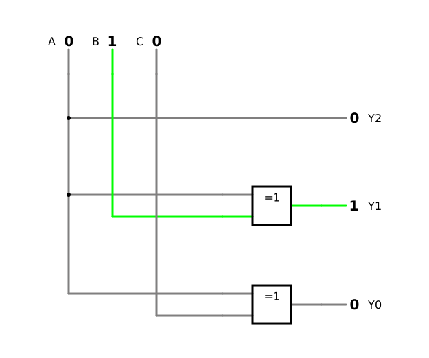
Example: a code converter from binary to Gray with a built-in fault (simulation). This code converter looks like the one in section 4.2 of this lesson. In the simulator, Y2 and Y1 agree with the code table in all eight rows, but Y0 deviates in the rows 2, 3, 4 and 5 (table). Y0 should be B⊕C; the deviating rows are exactly those in which A and B differ. So the XOR gate of Y0 does not receive B but A: the circuit delivers A⊕C.
On a 7-segment display, you see some faults at a glance, because the pattern does not look like a digit. Others hide. Example: a 7-segment display with a defective segment. If segment g fails, the 8 turns into a 0: the 7-segment display still looks plausible, and the fault shows only in a comparison with the code table or in a test of the segments. 7-segment display decoders such as the 74LS48 have a lamp test input for such a test, which lights all segments, so that you can see whether one of them has burned out [9, p. 117].
5 Selecting and distributing – Multiplexers and demultiplexers
5.1 The multiplexer
A multiplexer (German: Multiplexer) passes one of its data inputs (German: Dateneingänge) to its single output, chosen by its select inputs (German: Auswahleingänge); it works like a digital switch [5, p. 201]. With n select inputs, it has 2n data inputs [5, p. 201].
Steps 1 and 2 for a 2-to-1 multiplexer: data inputs I0 and I1, select input S, output Y. With S=0, the output follows I0; with S=1, it follows I1 [5, p. 201]:
S
Y
0
I0
1
I1
Steps 3 and 4 give [5, p. 201]:
Y=S⋅I0+S⋅I1
where:
Y is the output, 0 or 1
S is the select input, 0 or 1
I0 and I1 are the data inputs, each 0 or 1
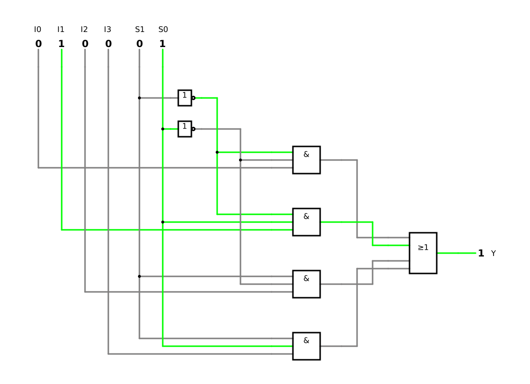
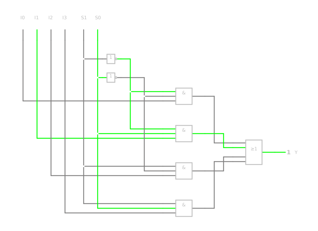
Read: Y equals I0 if S is 0, and I1 if S is 1. Step 5: two AND gates, an OR gate and an inverter [5, p. 201]. A 4-to-1 multiplexer has the two select inputs S1 and S0, and each of its four product terms contains both select inputs, so that only the selected AND gate passes its input to the OR gate [5, p. 202]:
S1 and S0 are the select inputs, each 0 or 1, S1 with the weight 2
I0 to I3 are the data inputs, each 0 or 1
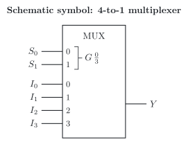
Many multiplexers also have an enable input (German: Freigabeeingang): as long as it does not enable the component, the output stays 0, whatever the select inputs say [12, pp. 111–112]. In the schematic symbol according to the standard of the International Electrotechnical Commission (IEC), IEC 60617, the qualifying symbol MUX marks a multiplexer [12, p. 112]. The select inputs are numbered 0 and 1 after the exponents of their weights 20 and 21, and the bracket G 0/3 says that the number they form selects one of the data inputs 0 to 3 through an AND dependency [12, pp. 112, 114] (figure).
Example: the hot-water set point of the heat pump. In operating state 3 of Smart Grid Ready (SG Ready), boost, our heat pump heats the hot water to the upper set point instead of the normal one. A 2-to-1 multiplexer for each bit of the set point could make this choice: its select input is the output Y1, boost, of the decoder of section 3.2 of this lesson, and its data inputs carry the two set points. The clock of section 1.3 of this lesson, which shows the time in the binary-coded decimal (BCD) code, contains a chip that can work as a multiplexer; section 5.3 of this lesson shows how.
A demultiplexer (German: Demultiplexer) works the other way round: it routes its single input to one of its several outputs, chosen by its select inputs; the outputs that are not selected are 0 [5, p. 203]. Lou and Yang therefore also call it a data distributor [9, p. 125]. With n select inputs, it has 2n outputs [5, p. 203].
Steps 1 and 2 for a 1-to-2 demultiplexer: input I, select input S, outputs Y0 and Y1 [5, p. 203]:
S
Y0
Y1
0
I
0
1
0
I
Steps 3 and 4 give [5, p. 203]:
Y0=S⋅IY1=S⋅I
where:
I is the input, 0 or 1
S is the select input, 0 or 1
Y0 and Y1 are the outputs, each 0 or 1
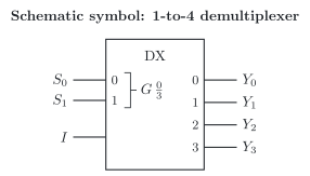
Read: the input reaches Y0 if S is 0, and Y1 if S is 1; the other output is 0. Step 5: two AND gates and an inverter [5, p. 203]. With its input at 1, a demultiplexer with two select inputs becomes a 2-to-4 decoder (section 3.1 of this lesson): each of its outputs is then a minterm of the select inputs [9, p. 125]. Conversely, a decoder can serve as a demultiplexer if one of its inputs carries the data [12, pp. 116–117]. In the schematic symbol according to IEC 60617, the qualifying symbol DX, or DMUX, marks a demultiplexer [30]; as in the multiplexer, the bracket G 0/3 combines the two select inputs of a 1-to-4 demultiplexer (figure).
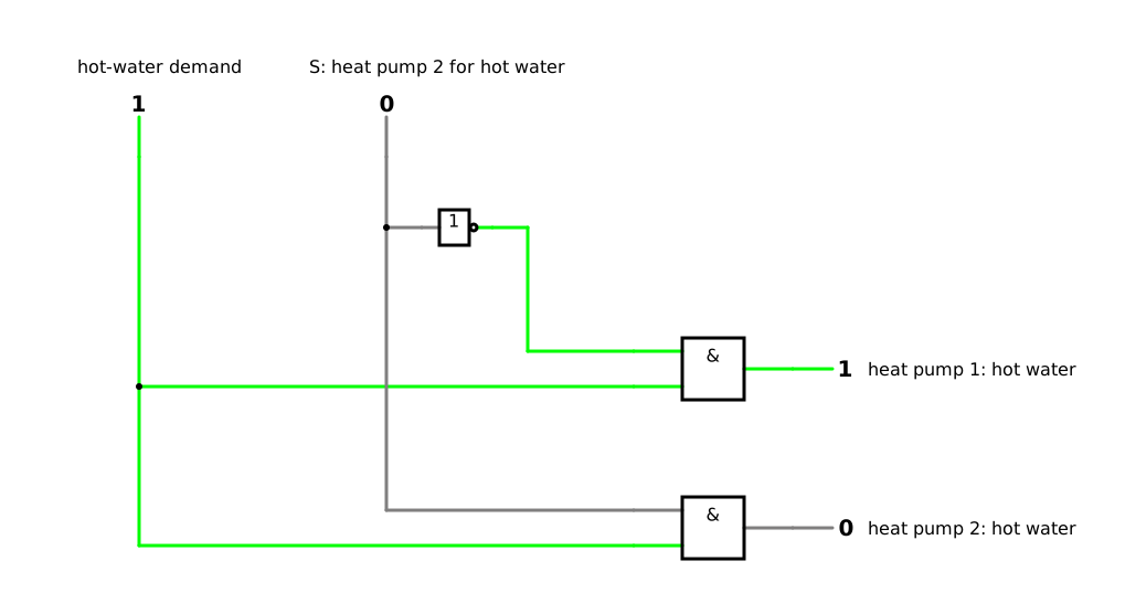
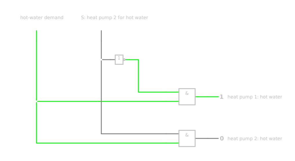
Example (third guiding question): two heat pumps, one shower. Our example system has two heat pumps in a cascade, with one common controller. For the hot water, the controller works with partial priority: the heat pump that is defined for hot water heats the hot-water tank, while the second one goes on heating the house. As a circuit, this choice is a 1-to-2 demultiplexer: its input is the hot-water demand, its select input says which heat pump is defined for hot water, and its outputs start the hot-water operation of heat pump 1 or of heat pump 2 (simulation). The heat pump whose output stays 0 remains free for the heating. In our system, the common controller makes this choice; the demultiplexer shows the logic behind it.
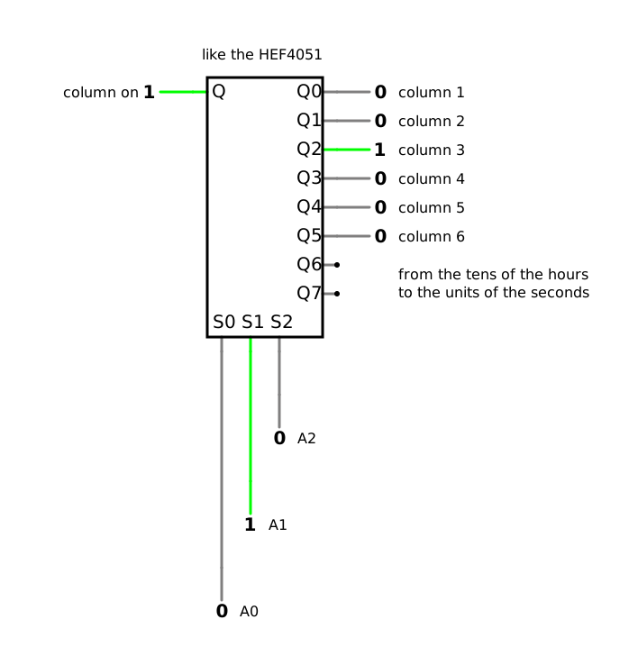
5.3 One chip, both directions: the HEF4051 in the BCD clock
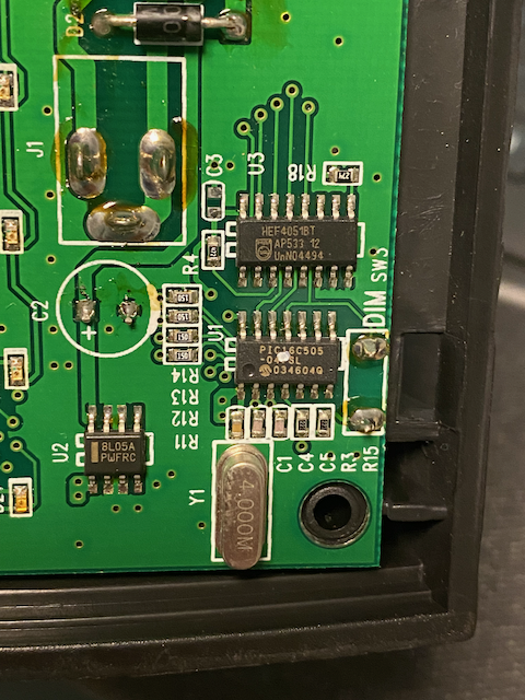
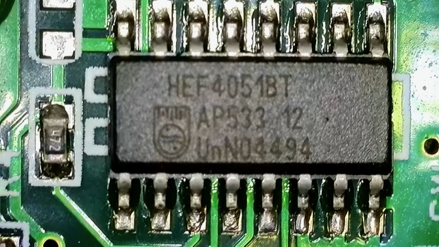
Example: the BCD clock. How does the BCD clock of section 1.3 of this lesson light its 20 light emitting diodes (LEDs)? Its circuit board carries a microcontroller and an integrated circuit HEF4051 (photo). The datasheet of the HEF4051 calls it an 8-channel analogue multiplexer/demultiplexer of medium-scale integration [29]. Inside, it contains eight bidirectional analogue switches (German: Analogschalter): one side of each switch is connected to one of eight independent inputs and outputs, the other side to a common input and output [29]. Three select inputs, which the datasheet calls address inputs, close one of the switches through a 3-to-8 decoder (section 3.1 of this lesson), as long as the enable input is 0; at 1, the enable input opens all switches [29]. Each switch is built from metal oxide semiconductor field-effect transistors (MOSFETs) of both types, which you know as switches from DET-02, 1.3 [29]. Because the switches conduct in both directions, the same chip works as an 8-to-1 multiplexer, from the eight pins to the common one, and as a 1-to-8 demultiplexer, from the common pin to the eight [29].
In the BCD clock, the HEF4051 works as a demultiplexer: it switches the six columns on one after another, so fast that your eye sees all lit LEDs at once. For each column, the microcontroller applies the BCD code word of its digit. Fricke describes this principle for a multiplexer and a demultiplexer whose select inputs run through all addresses again and again: each electric line at the inputs gets its own time slot, and the signals of all of them share a single electric line one after another [12, p. 117]. This is time-division multiplexing (German: Zeitmultiplex) [12, p. 117]. The clock saves electric lines in this way: it does not need one electric line for each of its 20 LEDs.
In the simulation, three logic inputs set the address of a column, and a demultiplexer with six used outputs switches this column on. Switch through the addresses 0 to 5 one after another, and you do by hand what the clock does much faster.
6 Any function from standard components – Logic functions with decoders and multiplexers
6.1 A decoder and an OR gate
So far, each standard component has done its own job. With few additions, they implement any logic function – step 5 of the synthesis (DET-03, 1.1), done with standard components instead of single gates. Each output of a decoder with n inputs and 2n outputs is 1 for exactly one code word: it is a minterm of the inputs (section 3.1 of this lesson). The OR of the outputs that belong to the ones of a function is therefore its canonical disjunctive normal form (DNF) (DET-03, 2.2) [12, pp. 117–118]. Steps 3 and 4 shrink to reading the minterm list; nothing is minimized.
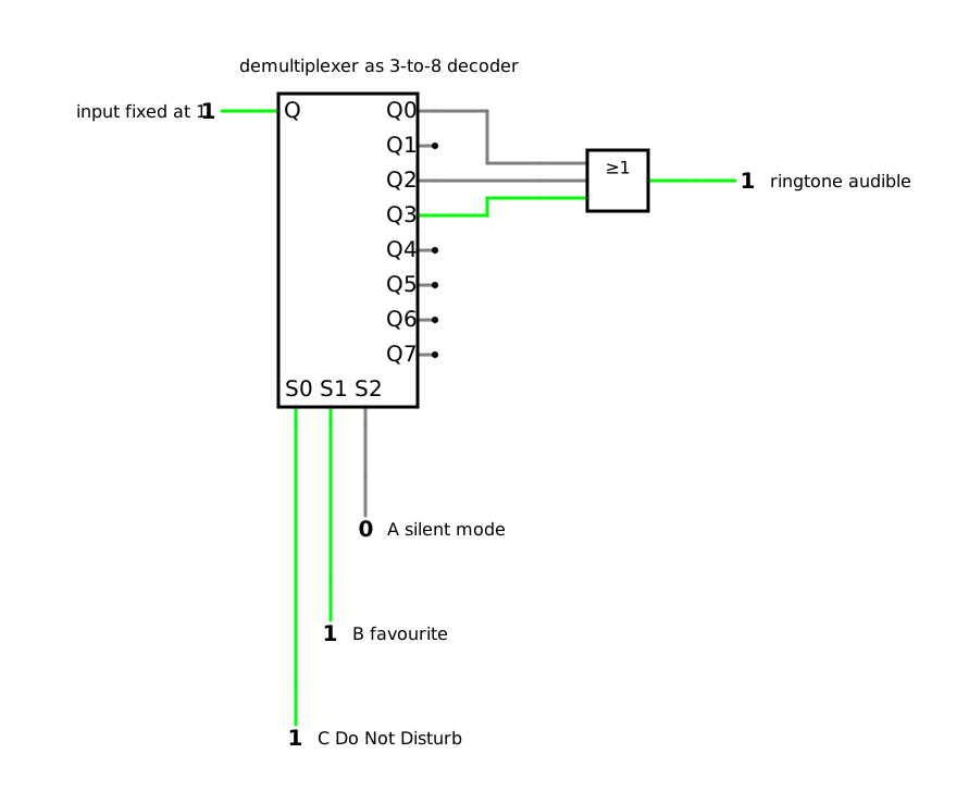
Example: the ringtone of your smartphone. In DET-03, 1.2, the ringtone was audible in the rows 0, 2 and 3 of its truth table, with A for silent mode, B for a favourite caller and C for Do Not Disturb:
Y(A,B,C)=∑m(0,2,3)
where:
Y is the output ‘ringtone audible’, 0 or 1
A, B and C are the inputs ‘silent mode on’, ‘caller is a favourite’ and ‘Do Not Disturb on’, each 0 or 1
m stands for the minterms, followed by the numbers of their rows
With a 3-to-8 decoder whose inputs are A, B and C, an OR gate with three inputs combines its outputs 0, 2 and 3 (simulation). The same decoder can produce further functions of the same inputs at the same time, each with its own OR gate [12, pp. 117–118]. Lou and Yang show the same procedure with an integrated decoder [9, pp. 111–112].
A multiplexer, too, implements any logic function: a 2n-to-1 multiplexer can implement any function of n input variables [9, p. 122]. The n variables go to the select inputs, and each data input is set to the output of its row of the truth table, 1 or 0 [9, p. 122]. For each combination of the inputs, the multiplexer then passes exactly the right value to its output: the truth table is wired at its data inputs.
Example: the ringtone again. With an 8-to-1 multiplexer, A, B and C go to the select inputs, and the data inputs I0 to I7 carry the column Y of the truth table: 1, 0, 1, 1, 0, 0, 0 and 0 (simulation). With one variable less at the select inputs, a 4-to-1 multiplexer suffices: A and B select, and each data input carries 0, 1, C or C [12, pp. 112–113], [9, p. 123]. For the ringtone, the rows with A:B = 0:0 have Y=1 for C=0 and Y=0 for C=1, so I0=C; the rows with 0:1 have Y=1 in both cases, so I1=1; the rows with 1:0 and 1:1 have Y=0, so I2=I3=0 (table).
A
B
Rows
Y for C=0 and C=1
Data input
0
0
0 and 1
1 and 0
I0=C
0
1
2 and 3
1 and 1
I1=1
1
0
4 and 5
0 and 0
I2=0
1
1
6 and 7
0 and 0
I3=0
Neither solution needs a minimization, and a different function needs only different connections, at the data inputs of the multiplexer or at the OR gate behind the decoder. DET-10 shows components whose connections you program instead of soldering them.
7 What have you learnt? – Summary and answers to the guiding questions
7.1 The building blocks of knowledge
Codes and coding: A code maps characters onto code words, and each code is made for its job: the binary code for calculating, the binary-coded decimal (BCD) code and the excess-3 code for decimal digits, for example on the light emitting diodes (LEDs) of the BCD clock, the Gray code for positions, the American Standard Code for Information Interchange (ASCII) and Code 39 for texts and labels, the Hamming code for correcting a flipped bit, the one-hot code for selecting exactly one of several outputs and the 7-segment code for displays. Redundancy, such as a parity bit, makes errors detectable: if any two code words differ in at least two positions, a flipped bit is detected; with at least three, it can even be corrected.
Code converters: A code converter turns one code into another. It is designed with the six steps of the synthesis, and code words that never occur become don’t cares. XOR gates convert between the binary code and the Gray code and compute the parity bits of the Hamming code. A built-in fault shows up when you compare the outputs with the code table row by row.
Standard components: A decoder sets one output for each code word, a 7-segment display decoder drives the segments of a digit, an encoder turns the active input into its code word, a multiplexer selects one of several data inputs and a demultiplexer distributes its input to one of several outputs. A decoder with an OR gate or a multiplexer implements any logic function.
With these building blocks, you choose a code for its job, design the circuit that converts it, and build logic from components that you can buy ready-made.
7.2 Answers to the guiding questions
Barcode, QR code, Morse code: why are there so many codes, and how do you choose the right one?
Because each code is made for a different job and a different medium [12, p. 3]: Morse code for signals by sound or light, a barcode such as Code 39 for a scanner, and inside digital systems the binary code for calculating, BCD for decimal digits, the Gray code for positions, ASCII for texts and the Hamming code for data that have to survive a flipped bit. You choose a code by what it has to represent, how it is transmitted or read, and which errors it has to detect or correct. The codes of this lesson at a glance:
Code
What it represents
What it is good for
Section
Binary code
numbers
calculating
1.2
BCD code, excess-3 code
decimal digits
displays, calculating with decimal digits
1.3
Gray code
positions
reading positions without errors
1.4
ASCII, Code 39
letters, digits and special characters
texts, labels
1.5
Hamming code
data bits with parity bits
correcting a flipped bit
2.2
One-hot code
one of several possibilities
selecting exactly one output
3.1
7-segment code
decimal digits for the eye
displays
3.3
Single LEDs on a BCD clock, glowing segments on a laboratory power supply: how does a number turn into light?
On the BCD clock, each column lights the BCD code word of its digit directly, with one LED for each weight that the column needs, and a demultiplexer switches the columns on one after another; you add the weights yourself. 7-segment displays, such as those on the laboratory power supply, show the shape of the digit instead; for this, a 7-segment display decoder turns the BCD code word of each digit into seven segment signals, minimized with the don’t cares of the unused code words.
Two heat pumps, one shower: which circuit decides which of them heats the water?
As a circuit, a 1-to-2 demultiplexer: with partial priority, the controller routes the hot-water demand to the heat pump that is defined for hot water, and the other heat pump goes on heating the house.
Where do I look things up? – Sources and references
All sources that I cite in this script with a number in square brackets, such as [5], are listed on the page References. There you will also find the books that I recommend for looking things up, the image licences and a note on the use of AI.