The camera app of a smartphone offers the flash settings Off, On and Auto. With Off, the flash never fires. With On, it fires for each photo. With Auto, it fires only if the scene is dark. In simplified form, the inputs and the output are:
A and B: the setting, A with the weight 2, with the code words 0:0 for Off, 0:1 for On and 1:0 for Auto; the code word 1:1 never occurs
C: the scene is dark
Y: the flash fires
Implement this function with standard components.
a) Set up the truth table of Y, and give the minterm list.
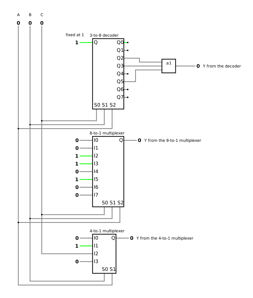
b) Implement Y with a 3-to-8 decoder and an OR gate. Which outputs of the decoder lead to the OR gate?
c) Implement Y with an 8-to-1 multiplexer. What do you connect to the data inputs I0 to I7?
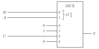
d) Implement Y with a 4-to-1 multiplexer, with A and B at the select inputs. What do you connect to the data inputs I0 to I3? Draw the circuit according to the standard of the International Electrotechnical Commission (IEC), IEC 60617.
e) Why does none of the three solutions need a minimization?
f) Suppose a software update gives the code word 1:1 a meaning: a fourth setting, with which the flash fires only if the scene is not dark. What do you have to change in each of the three solutions?
A multiplexer with the truth table at its data inputs, and with one variable less at the select inputs (DET-05)
Required
a) the truth table and the minterm list of Y
b) the outputs of the decoder that lead to the OR gate
c) the values at the eight data inputs
d) the values at the four data inputs, and the circuit
e) why no solution needs a minimization
f) what changes in each solution for the fourth setting
a) Truth table
With Off, in rows 0 and 1, Y is 0; with On, in rows 2 and 3, Y is 1; with Auto, in rows 4 and 5, Y equals C. The code word 1:1 never occurs, so rows 6 and 7 are don’t cares, marked X (DET-03, 4.4):
Row
A
B
C
Setting
Y
0
0
0
0
Off
0
1
0
0
1
Off
0
2
0
1
0
On
1
3
0
1
1
On
1
4
1
0
0
Auto
0
5
1
0
1
Auto
1
6
1
1
0
–
X
7
1
1
1
–
X
Y(A,B,C)=∑m(2,3,5)+d(6,7)
b) Decoder and OR gate
Each output of the 3-to-8 decoder is 1 for exactly one code word: it is a minterm of the inputs (DET-05, 6.1). With A, B and C at the inputs, A with the weight 4, an OR gate with three inputs over the outputs 2, 3 and 5 forms the canonical disjunctive normal form (DNF):
Y=A⋅B⋅C+A⋅B⋅C+A⋅B⋅C
The outputs 6 and 7 stay unconnected: rows 6 and 7 never occur, so the don’t cares simply become zeros here. The expression needs no gates of its own, because the decoder already delivers each minterm.
Check with row 5, Auto and a dark scene: the decoder sets its output 5 to 1, and the OR gate delivers Y=1 ✓
c) 8-to-1 multiplexer
A, B and C go to the select inputs, and each data input is set to the output of its row of the truth table (DET-05, 6.2):
Data input
I0
I1
I2
I3
I4
I5
I6
I7
Value
0
0
1
1
0
1
X
X
The don’t cares need a defined level at the input, so each X becomes a fixed value, here 0.
d) 4-to-1 multiplexer
With one variable less at the select inputs, A and B select one of four data inputs, and each data input carries 0, 1, C or C (DET-05, 6.2). Compare the two rows that belong to each select combination:
A
B
Rows
Y for C=0 and C=1
Data input
0
0
0 and 1
0 and 0
I0=0
0
1
2 and 3
1 and 1
I1=1
1
0
4 and 5
0 and 1
I2=C
1
1
6 and 7
X and X
I3: any fixed value, here 0
The multiplexer does just what the description says: the setting selects what the flash does (figure). C goes directly to I2; no inverter is needed, because C does not occur.
Check with Auto and a bright scene, row 4: A=1 and B=0 select I2=C=0, so Y=0, as in the truth table ✓
e) No minimization
Each of the three solutions takes the truth table as it is. The decoder delivers all minterms, and the OR gate only collects those that the function needs. The multiplexers do not form any terms at all: they select the values of the table, wired at their data inputs (DET-05, 6.2).
f) A fourth setting
The code word 1:1 now has a meaning: with C=0 the flash fires, and with C=1 it does not. Rows 6 and 7 are no longer don’t cares. For this new function Z, row 6 is 1 and row 7 is 0:
Z(A,B,C)=∑m(2,3,5,6)
Row
A
B
C
Z
0
0
0
0
0
1
0
0
1
0
2
0
1
0
1
3
0
1
1
1
4
1
0
0
0
5
1
0
1
1
6
1
1
0
1
7
1
1
1
0
Decoder and OR gate: lead the output 6 to the OR gate as well, which now has four inputs.
8-to-1 multiplexer: connect I6=1 and I7=0.
4-to-1 multiplexer: connect I3=C, with an inverter for C.
In all three solutions, only connections change; no expression has to be minimized again (DET-05, 6.2).
The simulation shows the three solutions of the original function side by side, all driven by the same inputs. Switch A, B and C through the rows of the truth table: the three outputs always agree.