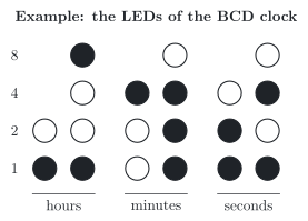
A clock in the binary-coded decimal (BCD) code shows the time with 20 light emitting diodes (LEDs) in six columns, for the tens and units of the hours, the minutes and the seconds. Each column shows one decimal digit in the BCD code, with the weights 8, 4, 2 and 1 from top to bottom:
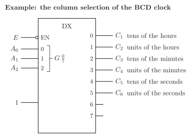
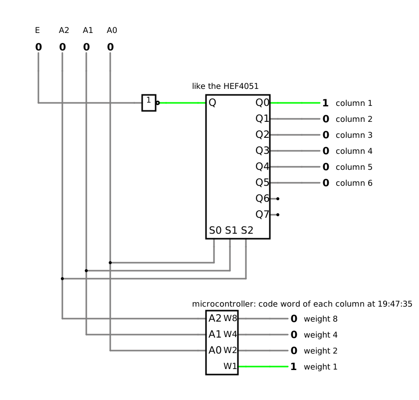
The clock does not drive all 20 LEDs at once. An integrated circuit HEF4051 works as a demultiplexer, and its outputs C1 to C6 switch the six columns on one after another. Its three address inputs select the column: the address 000 selects the tens of the hours, the address 101 the units of the seconds. As long as its enable input E is 0, it works; at E=1, no column is on. For each column, the microcontroller applies the BCD code word of its digit.
a) What time does the clock in the first figure show?
b) Fill in the gaps for this time. The table shows what happens in each of the six time slots.
A2
A1
A0
Column that is on
Digit
Weight 8
Weight 4
Weight 2
Weight 1
0
0
0
tens of the hours
1
0
0
0
1
0
0
1
units of the hours
0
1
0
tens of the minutes
0
1
1
1
0
0
1
0
1
c) Fill in the gaps in the truth table of the column selection, and give the logic expression of C3.
E
A2
A1
A0
C1
C2
C3
C4
C5
C6
0
0
0
0
1
0
0
0
0
0
0
0
1
0
0
1
0
1
0
1
1
0
1
1
0
1
d) Which LEDs are lit during the time slot with the address 011? Why does the clock not use the addresses 110 and 111?
e) How many electric lines lead from the microcontroller to the demultiplexer and to the LEDs in this way, if E stays at 0? How many would it need with one electric line for each LED?
f) Each column is on for one of six equal time slots. For which part of the time does an LED that belongs to a lit digit shine? Why do you still see all lit LEDs at once?
The HEF4051 in the clock and time-division multiplexing (DET-05)
Required
a) the time
b) the complete table of the six time slots
c) the complete truth table and the expression of C3
d) the lit LEDs for the address 011, and why the addresses 110 and 111 are not used
e) the number of electric lines in both cases
f) the part of the time and why you see all LEDs at once
a) Reading the time
Read the figure column by column, and add the weights of the lit LEDs (DET-05, 1.3):
Column
Lit weights
Digit
tens of the hours
1
1
units of the hours
8 + 1
9
tens of the minutes
4
4
units of the minutes
4 + 2 + 1
7
tens of the seconds
2 + 1
3
units of the seconds
4 + 1
5
Check: the tens of the hours do not exceed 2, and those of the minutes and seconds do not exceed 5, as the columns with two and three LEDs require ✓
b) The six time slots
The address selects the column, and the microcontroller applies the code word of its digit (DET-05, 5.3):
A2
A1
A0
Column that is on
Digit
Weight 8
Weight 4
Weight 2
Weight 1
0
0
0
tens of the hours
1
0
0
0
1
0
0
1
units of the hours
9
1
0
0
1
0
1
0
tens of the minutes
4
0
1
0
0
0
1
1
units of the minutes
7
0
1
1
1
1
0
0
tens of the seconds
3
0
0
1
1
1
0
1
units of the seconds
5
0
1
0
1
c) Truth table of the column selection
Each output of the demultiplexer is 1 for exactly one address, as long as E is 0. The input is fixed at 1, so the outputs are the minterms of the address inputs, as in a decoder (DET-05, 5.2), and the enable input is a further condition:
Check with the address 010: only C3 is 1, and the third column, the tens of the minutes, is the one with the address 2 ✓
d) The time slot with the address 011
The address 011 is the number 3, and this selects column 4, the units of the minutes. The digit 7 has the code word 0111, so the LEDs with the weights 4, 2 and 1 of this column are lit. All other columns are off during this time slot.
The clock has six columns, and three address inputs give eight addresses. The addresses 110 and 111 would select the outputs 6 and 7, which are connected to nothing, so the clock has no use for them.
e) Number of electric lines
In each time slot, the code word needs four electric lines, one for each weight, and the address needs three. With E at 0, this makes 4+3=7 electric lines from the microcontroller. With one electric line for each LED, it would need 20. This is the saving that time-division multiplexing brings (DET-05, 5.3).
f) Part of the time
Each column gets one of six equal time slots, so an LED of a lit digit shines for one sixth of the time. The clock runs through the columns so fast that your eye cannot follow, and you see all lit LEDs at once (DET-05, 5.3).
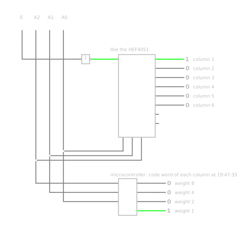
The simulation shows the column selection and, as a block, the microcontroller with the code words of the time 19:47:35. Switch the address inputs through the addresses 000 to 101 and compare with the table of b). You do by hand what the clock does much faster. With E at 1, no column is on, whatever the address says.