In the previous lesson, you designed circuits from a description of what they are to do.
Six steps lead from the description to the checked circuit: inputs and outputs, truth table, normal form, minimization, circuit or VHDL, and the check against the description.
The canonical disjunctive normal form (DNF) is the OR of the minterms of all ones, the canonical conjunctive normal form (CNF) the AND of the maxterms of all zeros; the minterm list writes a function in short.
Boolean algebra and the Karnaugh map minimize an expression. In the map, loops of neighbouring ones yield the product terms of a minimized DNF, and don’t cares enlarge the loops.
Two circuits do the same job if their truth tables or their minterm lists agree.
Today, we ask which loops a minimal expression really needs, how a computer finds them without a map, and why a correct circuit can still deliver a wrong value for a few nanoseconds.
1 Which loops are really needed? – Prime implicants
1.1 Implicants and prime implicants
In DET-03, 4.2, you drew loops around neighbouring ones in the Karnaugh map, each as large as possible. Today, you learn what LaMeres means by a prime implicant and which loops a minimal expression really needs. Both belong to step 4 of the synthesis, the minimization (DET-03, 1.1); the next two chapters of this lesson stay with this step. Our example is the display of your smartphone, with two rules that you know from DET-02. During a call, the display switches off as soon as the proximity sensor next to the earpiece is covered, and it stays on while the sensor is free, so that you can see it when you talk over the loudspeaker (DET-02, 2.1). Outside a call, it switches on if you press the power button or lift the phone (DET-02, 3.3). The display, the example of this chapter, has four inputs and one output:
A: a call is active
B: the proximity sensor is covered
C: the power button is pressed
D: the phone is lifted
Y: the display is on
In DET-02, 6.1, the display needed the button or the lift during a call as well; here, the sensor alone decides during a call. In the rows of the truth table with A=0, the display is on if C=1 or D=1; in the rows with A=1, it is on if B=0.
Row
A
B
C
D
Y
0
0
0
0
0
0
1
0
0
0
1
1
2
0
0
1
0
1
3
0
0
1
1
1
4
0
1
0
0
0
5
0
1
0
1
1
6
0
1
1
0
1
7
0
1
1
1
1
8
1
0
0
0
1
9
1
0
0
1
1
10
1
0
1
0
1
11
1
0
1
1
1
12
1
1
0
0
0
13
1
1
0
1
0
14
1
1
1
0
0
15
1
1
1
1
0
In rows 12 to 15, your ear covers the sensor during a call, and the display stays dark even if your cheek presses the button. The function has ten ones:
Y(A,B,C,D)=∑m(1,2,3,5,6,7,8,9,10,11)
where:
Y is the output ‘display on’, 0 or 1
A, B, C and D are the inputs ‘call active’, ‘proximity sensor covered’, ‘power button pressed’ and ‘phone lifted’, each 0 or 1
m stands for the minterms, followed by the numbers of their rows
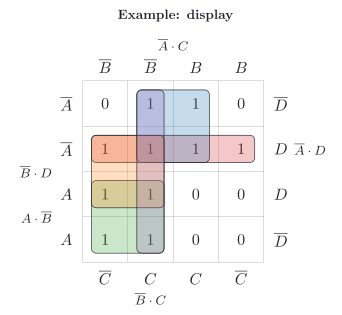
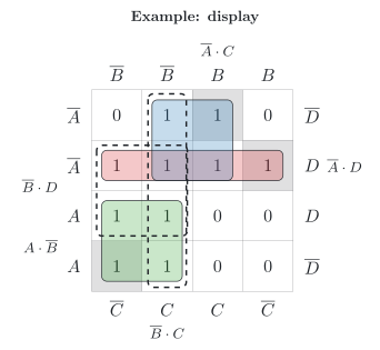
In the map (figure), each loop stands for a product term that is 1 in the cells of the loop and 0 everywhere else. Since all these cells contain a one, Y is 1 whenever the term is 1: the term implies the function and is an implicant (German: Implikant) of it [17, p. 18], [12, p. 54]. Each single one is an implicant, and so is each loop of ones. An implicant that no larger implicant contains – a loop that cannot be enlarged – is a prime implicant (German: Primimplikant) [12, p. 55], [5, p. 130]. Your rule ‘each loop as large as possible’ therefore yields exactly the prime implicants. The display has five of them:
A⋅D: no call, phone lifted (minterms 1, 3, 5 and 7)
A⋅C: no call, button pressed (minterms 2, 3, 6 and 7)
Read the last one: if the sensor is free and you press the button, the display is on – with or without a call. That is true, but section 1.2 shows that the minimal expression does not need it.
1.2 Essential and redundant prime implicants
Not every prime implicant is needed. Look for ones that only a single prime implicant covers: the one of minterm 5 – no call, sensor covered, button not pressed, phone lifted – lies only in A⋅D, the one of minterm 6 only in A⋅C, and the one of minterm 8 only in A⋅B. Without these three prime implicants, these ones would be missing. A prime implicant that covers a one that no other prime implicant covers is an essential prime implicant (German: Kernprimimplikant) [5, p. 138], [12, p. 55]. It appears in every minimal expression [12, p. 55].
The three essential prime implicants of the display together cover all ten ones. In the figure, they are drawn with solid lines, and the three ones that only a single prime implicant covers are shaded. The ones of B⋅D – minterms 1, 3, 9 and 11 – already lie in A⋅D and A⋅B, and those of B⋅C – minterms 2, 3, 10 and 11 – in A⋅C and A⋅B. A prime implicant whose ones the essential prime implicants cover completely is superfluous [12, p. 55]: a redundant prime implicant (German: absolut eliminierbarer Primimplikant) [17, p. 41], [12, p. 55]. It can be left out; the figure draws the two redundant prime implicants with dashed lines. What remains is the minimal disjunctive normal form (DNF, German: minimale disjunktive Normalform) [12, p. 53] of the display:
Y=A⋅C+A⋅D+A⋅B
where:
Y is the output ‘display on’, 0 or 1
A, B, C and D are the inputs ‘call active’, ‘proximity sensor covered’, ‘power button pressed’ and ‘phone lifted’, each 0 or 1
Read: the display is on if, outside a call, the button is pressed or the phone is lifted, or if, during a call, the sensor is free – the description of section 1.1 in three product terms. Counted as in DET-03, 3.1, the circuit needs three AND gates with two inputs each and an OR gate with three inputs, plus inverters for A and B. The canonical DNF would need ten AND gates with four inputs each and an OR gate with ten inputs.
LaMeres calls the minimal DNF the minimal sum, and the OR of all prime implicants the complete sum [5, p. 138]; for the display, the complete sum has five product terms. Keep the two redundant prime implicants in mind: in chapter 4, they will be needed after all.
1.3 When there is a choice
For the display, the essential prime implicants cover every one, and there is exactly one minimal DNF. That is not always so. If some ones remain that no essential prime implicant covers, a selection of the other prime implicants has to cover them, with as few as possible [12, pp. 56, 62]. Fricke shows this with a function of four inputs [12, pp. 53–56]:
Y(A,B,C,D)=∑m(0,2,5,8,10,12,13,15)
where:
Y is the output, 0 or 1
A, B, C and D are the inputs, each 0 or 1, with A as the variable of the highest weight
m stands for the minterms, followed by the numbers of their rows
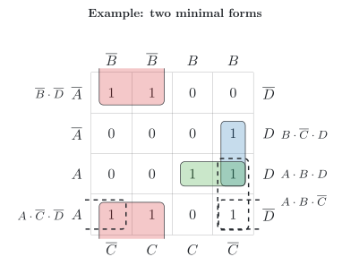
Its map (figure) has five prime implicants. Three of them are essential and are drawn with solid lines: B⋅D with the four cells 0, 2, 8 and 10, because only it covers 0, 2 and 10; B⋅C⋅D with 5 and 13, because only it covers 5; and A⋅B⋅D with 13 and 15, because only it covers 15. Together, they leave the one of minterm 12 uncovered. Two prime implicants contain it, both drawn with dashed lines: A⋅B⋅C with 12 and 13, and A⋅C⋅D with 8 and 12, which are neighbours across the left and the right edge of the map. Either of them completes the minimal DNF, and the two forms are of the same size, with four product terms each [12, p. 56]:
YY=B⋅D+B⋅C⋅D+A⋅B⋅D+A⋅B⋅C=B⋅D+B⋅C⋅D+A⋅B⋅D+A⋅C⋅D
where:
Y is the output, 0 or 1
A, B, C and D are the inputs, each 0 or 1
So a function can have more than one minimal DNF; LaMeres, too, notes that there may be several minimal sums, all with the same number of operations [5, p. 138]. The canonical DNF, in contrast, is unique (DET-03, 2.5):
Form
Product terms
Unique?
Canonical DNF
the minterms of all ones, each with every variable
yes
Minimal DNF
the essential prime implicants and, if needed, a selection of the others
not always
The choice also sharpens a rule from DET-03, 4.2: a loop whose ones all lie in other loops is not needed. Here, each of the two loops A⋅B⋅C and A⋅C⋅D fulfils this condition, because the other one covers cell 12. You may leave out one of them, but not both – cell 12 would then remain uncovered.
Erratum in the textbook by LaMeres
LaMeres [5, pp. 138, 145] states that the minimal sum consists of the essential prime implicants alone. This holds only if they cover all ones. In the example above, they leave minterm 12 uncovered, and one of the other prime implicants has to complete the minimal form [12, p. 56].
2 Recipe for a computer – The Quine–McCluskey algorithm
2.1 From the map to the table
The map relies on your eye: you see neighbours and large loops at a glance. A computer does not see a picture; it needs rules that it can follow one after another. The Quine–McCluskey algorithm (German: Quine-McCluskey-Verfahren) puts the map into tables [17, pp. 115–116] and is therefore suited to implementation on a computer [12, p. 60], [18, p. 136]. Like the map, it relies on the uniting theorem of DET-03, 3.2: two product terms that differ in only one variable unite into one without this variable [12, p. 60]. The algorithm works in two parts: part 1 finds all prime implicants, and part 2 selects the fewest of them that cover all ones [18, p. 136]. Both parts work with tables: part 1 builds one table after another, and part 2 adds one more table, which section 2.3 introduces [12, pp. 60–61].
The algorithm writes each minterm as its code: a 1 for a variable that appears as it is, a 0 for a negated variable and a dash for a variable that has dropped out [12, p. 60]. Minterm 3 of the display, A⋅B⋅C⋅D, is written 0011; the product term A⋅D is written 0‑‑1.
Then it sorts the minterms into groups by the number of their ones [12, p. 60]. Two codes that differ in exactly one position always lie in consecutive groups, because one of them has exactly one 1 more than the other. The algorithm therefore compares only terms of consecutive groups, and this saves many comparisons [17, p. 118]. For the ten ones of the display from section 1.1, this gives the first table, with three groups:
Group
Minterm
A
B
C
D
1
1
0
0
0
1
1
2
0
0
1
0
1
8
1
0
0
0
2
3
0
0
1
1
2
5
0
1
0
1
2
6
0
1
1
0
2
9
1
0
0
1
2
10
1
0
1
0
3
7
0
1
1
1
3
11
1
0
1
1
Minterm 1 of group 1, for example, only needs to be compared with the five minterms of group 2, not with the two of group 3: a code with three ones cannot differ from 0001 in only one position.
Quine and McCluskey
Quine described the method in 1952, and McCluskey extended it in 1956 [19]. Donzellini and his co-authors count it among the earliest algorithms that minimize Boolean expressions [17, p. 115].
2.2 Part 1: finding all prime implicants
Part 1 builds one table after another, starting from the first table. To form the next table, the algorithm compares each term of a group with each term of the next group. If two terms differ in exactly one position, it writes the united term into the next table, with a dash in this position and the numbers of both minterms, and ticks both terms in the previous table [12, pp. 60–61]. Minterm 1 (0001) and minterm 3 (0011), for example, differ only in C and unite into 00-1, the term A⋅B⋅D. For the display, the second table holds 14 pairs:
Group
Minterms
A
B
C
D
1
1, 3
0
0
-
1
1
1, 5
0
-
0
1
1
1, 9
-
0
0
1
1
2, 3
0
0
1
-
1
2, 6
0
-
1
0
1
2, 10
-
0
1
0
1
8, 9
1
0
0
-
1
8, 10
1
0
-
0
2
3, 7
0
-
1
1
2
3, 11
-
0
1
1
2
5, 7
0
1
-
1
2
6, 7
0
1
1
-
2
9, 11
1
0
-
1
2
10, 11
1
0
1
-
Every minterm has found at least one partner, so none of them is a prime implicant. For the third table, the algorithm applies the same rule to the pairs: two terms unite if their dashes stand in the same position and they differ in exactly one other position [12, p. 61]. 00-1 (1, 3) and 01-1 (5, 7) unite into 0‑‑1 (1, 3, 5, 7), the term A⋅D. The same term also comes from 0-01 (1, 5) and 0-11 (3, 7); a term that appears more than once is kept only once [12, p. 61], [17, p. 119]:
Minterms
A
B
C
D
Term
1, 3, 5, 7
0
-
-
1
A⋅D
1, 3, 9, 11
-
0
-
1
B⋅D
2, 3, 6, 7
0
-
1
-
A⋅C
2, 3, 10, 11
-
0
1
-
B⋅C
8, 9, 10, 11
1
0
-
-
A⋅B
All 14 pairs are now ticked. The code of each of the five terms that cover four minterms has exactly one 1, so all five fall into the same group; there is no next group, and part 1 ends, because no terms can be united any more [12, p. 61]. Every term without a tick is a prime implicant [12, p. 61]. Here, these are the five terms of the third table – exactly the five loops of section 1.1. The algorithm has found them without a picture, in three tables: ten minterms, 14 pairs and five terms that cover four minterms each.
2.3 Part 2: selecting with the prime implicant chart
Part 2 selects the prime implicants for the minimal expression. For this, they are entered in one more table, the prime implicant chart (German: Primimplikantentafel) [12, p. 61], [19]: one row for each prime implicant, one column for each minterm, and a mark wherever the prime implicant contains the minterm [12, p. 62]. For the display:
Prime implicant
1
2
3
5
6
7
8
9
10
11
A⋅D
●
●
●
●
A⋅C
●
●
●
●
A⋅B
●
●
●
●
B⋅D
●
●
●
●
B⋅C
●
●
●
●
A column with a single mark belongs to a minterm that only one prime implicant covers; this prime implicant is essential [12, p. 62], [17, p. 119]. In the chart of the display, the columns 5, 6 and 8 have a single mark each: A⋅D, A⋅C and A⋅B are essential. Their rows have marks in all ten columns, so every minterm is covered. The rows of B⋅D and B⋅C are not needed, and the algorithm ends with the minimal disjunctive normal form (DNF) of section 1.2, Y=A⋅C+A⋅D+A⋅B – the same result as the map, found without looking at a picture.
If minterms remain uncovered after the essential prime implicants, the algorithm selects as few of the other prime implicants as possible to cover them [12, p. 62]. In the example of section 1.3, the column of minterm 12 remains, and two rows can cover it; the chart then shows the choice between the two minimal forms [12, pp. 62–63].
3 Six signals for a heat pump – Functions with many inputs
3.1 When the map becomes too large
Now to our heat pump and the third guiding question: six signals decide whether it may start. In our example system, the energy supplier can block the heat pump; as long as the block lasts, the heat pump must not start (DET-02, 3.1) [13], and only frost protection is ensured: frost protection may start the heat pump even during a block. Above an outside temperature of 19 °C, the controller switches to summer mode, in which the heating is off and the heat pump only heats the hot water. Below the bivalence temperature of −7 °C, a second heat generator heats alone, and the heat pump only starts for the hot water and for frost protection.
In simplified form, the controller therefore follows this rule: frost protection may always start the heat pump. Without a block, a hot-water demand starts it in every season, and a heating demand starts it outside summer mode and above the bivalence temperature. The six inputs and the output are:
A: the heating demands heat
B: the hot water demands heat
C: summer mode is on
D: the energy supplier blocks the heat pump
E: the outside temperature is below the bivalence temperature
F: frost protection is active
Y: the heat pump may start
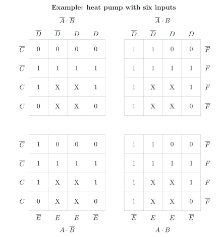
With six inputs, the truth table has 26=64 rows, and the map has 64 cells. A map for six inputs consists of four maps for four inputs, and a cell has neighbours not only next to it but also in the other maps [17, pp. 40–41]; Fricke draws it with 8 × 8 cells [12, p. 58]. The figure shows our heat pump in this form: each of the four maps stands for one combination of A and B, and inside each map, the inputs C, D, E and F are arranged like A, B, C and D in the map of the display.
Some combinations never occur: the outside temperature cannot be above 19 °C and below −7 °C at the same time. In the 16 rows with C=1 and E=1, the output is therefore a don’t care, as in DET-03, 4.4, marked X in the map. Of the other 48 rows, 31 demand a 1 and 17 a 0.
Finding the largest loops among 64 cells by eye, also across the borders of the four maps, is error-prone. Reichardt considers the map well suited to the human eye for up to five inputs [18, p. 136], and maps with more than six variables are rarely used, because they become very unclear [12, p. 57]. Donzellini and his co-authors draw the line even earlier: for more than four variables, they leave the minimization to algorithms on a computer [17, p. 115].
3.2 The algorithm with many inputs
The algorithm does not care how many inputs there are: its two parts stay the same, only the tables grow. Don’t cares count as ones while terms are united, so that the united terms become as large as possible, and they get no column in the prime implicant chart, because they need not be covered [17, p. 120]. For the heat pump, a computer program carries out the algorithm. Part 1 needs six tables:
Table
Terms
Minterms per term
Prime implicants found
1
47
1
–
2
119
2
–
3
116
4
A⋅C⋅D⋅E
4
54
8
–
5
12
16
B⋅D and C⋅E
6
1
32
F
In the first table, the 31 ones and the 16 don’t cares are 47 minterms in six groups. Each further table unites terms into terms that cover twice as many minterms, until the sixth table holds a single term with 32 minterms. Four prime implicants have no partner: A⋅C⋅D⋅E, B⋅D, C⋅E and F. The term C⋅E contains only don’t cares, the combinations that never occur, and has nothing to cover in the chart. The other three are essential, and the minimal disjunctive normal form (DNF) has three product terms:
Y=F+B⋅D+A⋅C⋅D⋅E
where:
Y is the output ‘heat pump may start’, 0 or 1
A and B are the inputs ‘heating demands heat’ and ‘hot water demands heat’, each 0 or 1
C and D are the inputs ‘summer mode on’ and ‘energy supplier blocks the heat pump’, each 0 or 1
E and F are the inputs ‘below the bivalence temperature’ and ‘frost protection active’, each 0 or 1
Read: the heat pump may start if frost protection is active, or if the hot water demands heat without a block, or if the heating demands heat without a block, outside summer mode and above the bivalence temperature. Two AND gates, an OR gate with three inputs and three inverters replace a canonical DNF with 31 AND gates of six inputs each. Here, the don’t cares keep the result short: F and B⋅D may include the combinations that never occur. With a 0 in these cells, the minimal DNF would need five product terms. The don’t cares also add the prime implicant C⋅E, which the chart leaves out.
The effort, however, grows quickly. With every further input, the number of rows doubles, and the effort of the algorithm grows exponentially with the number of inputs [18, p. 137], [19]. According to Reichardt, it can realistically be computed for 15 to 20 inputs at most [18, p. 137]. Part 2 can grow as well: if k prime implicants remain after the essential ones, trying every selection means 2k−1 cases, although the algorithm has ways that usually need far fewer [17, pp. 120–121].
3.3 Logic minimization software: exact and heuristic
For large functions, even the exact algorithm reaches its limits. For two-level minimization (German: zweistufige Minimierung), the search for a minimal DNF or a minimal conjunctive normal form (CNF), Reichardt names two algorithms for the computer: the Quine–McCluskey algorithm, which is exact, and the Espresso heuristic logic minimizer, Espresso for short, which is heuristic [18, pp. 136–137]. A heuristic method (German: heuristisches Verfahren) works with simplifying assumptions: as a rule, it reaches the same result as the exact algorithm, but in individual cases, the solution that it finds is slightly off the optimum [18, p. 137]. Because its effort is much lower, Espresso in its version II has become established for two-level minimization [18, p. 137].
You met such software in DET-03, 6.3: a synthesis tool (German: Synthesewerkzeug), the software that turns VHDL code into a circuit, looks for an inexpensive circuit itself, and according to LaMeres, computer automation is often the best way to minimize large expressions [5, p. 126]. So the answer to the first guiding question is yes – a computer can minimize a circuit for you: exactly with the Quine–McCluskey algorithm as long as the number of inputs allows it, and with heuristics beyond that. It is still worth understanding what the computer does: chapter 4 of this lesson shows a case in which the minimal circuit is not the best one.
4 Dark for a few nanoseconds – Hazards
4.1 Static and dynamic hazards
So far, our circuits have switched without delay. In DET-02, 3.5, however, you saw that a real gate needs a few nanoseconds to follow its inputs, its propagation delay, and in DET-02, 6.3, that the delays add up along each path through a circuit. Different paths therefore have different delays, and while the inputs change, the output can show short, unwanted pulses. The check against the description, step 6 of the synthesis (DET-03, 5.2), compared truth tables, that is, the values after all changes have settled; it does not see these pulses. These pulses are the hazards [5, p. 142] that I announced in DET-01, 5.2; LaMeres also calls them glitches [5, p. 142].
Hazards are named after what the output should do (figure) [5, p. 143], [12, p. 68]:
A static 1 hazard (German: statischer 1-Hazard): the output should stay 1, but drops to 0 for a moment.
A static 0 hazard (German: statischer 0-Hazard): the output should stay 0, but rises to 1 for a moment.
A dynamic hazard (German: dynamischer Hazard): the output should change once, from 0 to 1 or from 1 to 0, but changes several times before it reaches its final value.
A hazard comes from a race (German: Wettlauf) [9, p. 130]: either several inputs change at the same moment, and their changes arrive one after another, or a single input reaches a gate on two paths with different delays [9, p. 130]. Fricke treats the two cases separately [12, pp. 66–68]. A hazard caused by the change of a single input depends on the structure of the circuit [18, p. 134] and is called a logic hazard (German: Strukturhazard) [12, p. 66], [20]. A hazard caused by the change of several inputs is a function hazard (German: Funktionshazard) [12, p. 67], [20]. LaMeres does not distinguish the two kinds [5, pp. 142–144]. Sections 4.2 and 4.3 deal with the logic hazard, section 4.4 with the function hazard.
4.2 One input, two paths
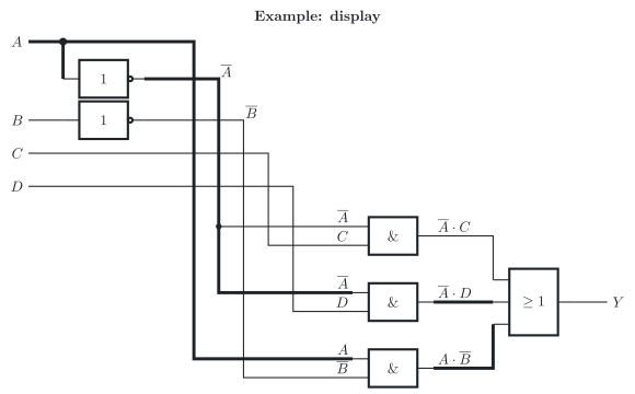
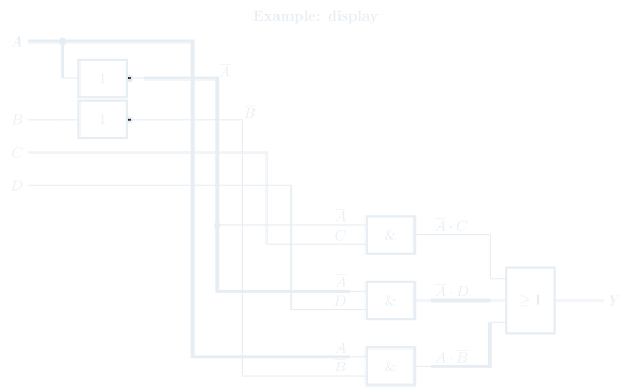
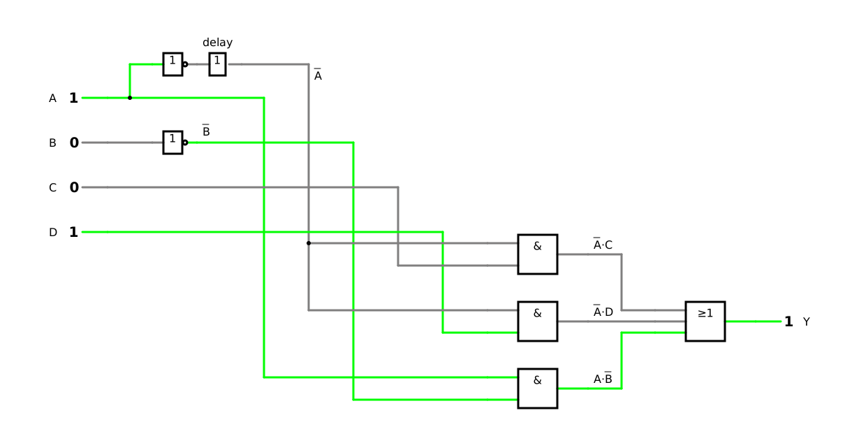
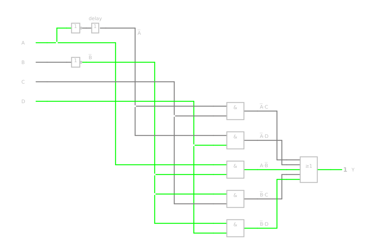
Back to the display of chapter 1, built as a two-level circuit from its minimal disjunctive normal form (DNF), Y=A⋅C+A⋅D+A⋅B (figure): two inverters form A and B, three AND gates form the product terms, and an OR gate combines them into Y. The thick lines mark the two paths on which the input A reaches the OR gate.
You end a call while you hold the phone in front of you: A changes from 1 to 0, while B=0, C=0 and D=1. Before, the display is on because the sensor is free during the call, A⋅B=1; afterwards, it is on because the phone is lifted, A⋅D=1. The output should stay 1.
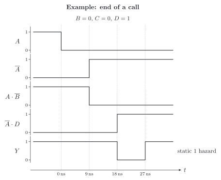
Suppose, as in DET-02, 6.3, that each gate has a propagation delay of 9 ns, the typical value of the NAND gates of the 74HC00 [11]. Follow the change through the circuit (timing diagram):
At t=0, A falls from 1 to 0.
After 9 ns, the output of the AND gate for A⋅B has followed and is 0.
A comes from an inverter and rises only after 9 ns; the AND gate for A⋅D needs another 9 ns, so its output rises after 18 ns.
Between 9 ns and 18 ns, all three inputs of the OR gate are 0. With its own delay, the output Y is 0 from 18 ns to 27 ns.
For 9 ns, the display signal drops to 0 although it should stay 1: a static 1 hazard. Its cause is the inverter. The input A reaches the OR gate on the two thick paths of the circuit, directly through A⋅B and through the inverter and A⋅D, and the second path is slower. Lou and Yang call such a contest between paths a race [9, p. 130]; LaMeres [5, p. 142] and Fricke [12, p. 66] show the same effect with other examples. When the call starts, A rises: A⋅B becomes 1 after 9 ns, before A⋅D becomes 0 after 18 ns, and there is no dip.
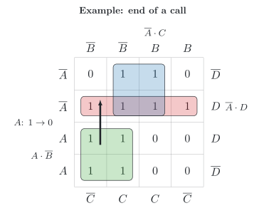
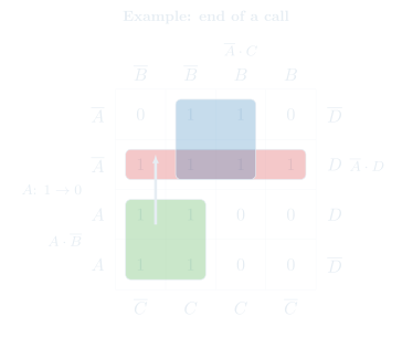
In the map (figure), the change of A leads from the cell of minterm 9 to the neighbouring cell of minterm 1. Both cells contain a one, but in the minimal DNF they belong to different loops, A⋅B and A⋅D, and no loop of the minimal DNF contains both. This is the mark of a logic hazard in a two-level circuit of AND gates and an OR gate: two neighbouring ones that do not lie in a common loop [17, p. 68], [12, p. 67].
Nobody would see a dip of 9 ns on the display. Whether such a dip does harm depends on what the signal drives; chapter 5 returns to this question. In the simulator, a delay element enlarges the delay of the inverter on purpose, so that you can watch the dip: switch A from 1 to 0 with B=0 and D=1, and Y goes dark for a moment. Without such a delay element, the dip lasts only 5 µs in the simulation.
4.3 Hazard analysis: the redundant prime implicant returns
A hazard analysis (German: Hazard-Analyse) finds such places and removes them before they do harm. For logic hazards in a two-level circuit, Reichardt recommends the following procedure [18, p. 135]:
Set up the minimal disjunctive normal form (DNF) or conjunctive normal form (CNF).
Determine for each prime implicant used whether the change of a single input leads from it to a second, completely separate prime implicant.
Add redundant prime implicants that unite the prime implicants found in point 2.
For point 2, it helps to look for a variable that appears as it is in one product term and negated in another [12, p. 67], [9, p. 131]. If the other variables are set so that both terms reduce to this variable, the expression becomes A+A: always 1 in theory, but in practice possibly 0 for a moment [9, pp. 130–131]. In the minimal DNF of the display, only A appears in both forms: negated in A⋅C and A⋅D, as it is in A⋅B. Two changes of A therefore lead between separate prime implicants:
from A⋅B to A⋅D, if B=0 and D=1 – the redundant prime implicant B⋅D unites them;
from A⋅B to A⋅C, if B=0 and C=1 – the redundant prime implicant B⋅C unites them.
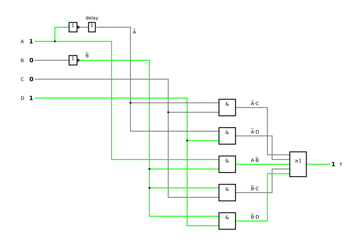
These are exactly the two redundant prime implicants that we left out in section 1.2. Added to the minimal DNF, they make the display circuit free of logic hazards:
Y=A⋅C+A⋅D+A⋅B+B⋅C+B⋅D
where:
Y is the output ‘display on’, 0 or 1
A, B, C and D are the inputs ‘call active’, ‘proximity sensor covered’, ‘power button pressed’ and ‘phone lifted’, each 0 or 1
While A changes with B=0 and D=1, the term B⋅D does not depend on A and stays 1; it holds the output at 1, however the delays turn out. LaMeres removes hazards in the same way, with the complete sum of all prime implicants [5, p. 143]; Donzellini and his co-authors show it with a multiplexer [17, pp. 67–69]. In the simulator, switch A from 1 to 0 again with B=0 and D=1: now Y stays 1.
The price is two more AND gates, and the circuit is no longer minimal [17, p. 69]. One more caveat: the synthesis tools for programmable devices usually optimize redundant prime implicants away again [18, p. 135]. There, hazard-free signals are produced with flip-flops [18, p. 135], which you will meet in DET-06.
4.4 Two inputs at once: the function hazard
The redundant prime implicant helps when a single input changes. If several inputs change at the same moment, a hazard can arise that no additional term removes. Fricke shows this with a Karnaugh map in which two inputs change together. The inputs then take one of two ways through the map, depending on which of them acts first: on one way, the output stays 1; on the other, the way passes through a cell with a 0, and a hazard appears [12, pp. 67–68].
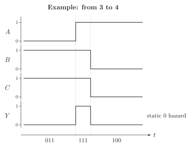
You know an example from counting in binary (DET-01, 6.3). A counter with the three bits A, B and C, with A as the bit of the highest weight, goes from 3 to 4, that is, from 011 to 100: all three bits change. Suppose a gate is to report that the count has reached 6 or more, Y=A⋅B. At 3 and at 4, Y=0. But the three bits never change at exactly the same moment. If A becomes 1 before B becomes 0, the gate sees 111 or 110 for a moment, and Y delivers a short 1 (figure): a static 0 hazard.
Why can no additional term remove this pulse? The combinations that the gate passes through on its way, 111 and 110, are combinations for which the function itself demands Y=1. An additional product term can only add ones; it cannot remove a one that the function demands. Whether the pulse appears depends on the order in which the bits arrive. No additional term can remove such a hazard; there is no logical solution for it [20]. It is avoided by reading the output only when all changes have settled, or by making sure that the inputs never change at the same time [20]. Circuits that read their signals only at moments given by a clock can therefore generally tolerate hazards [17, p. 70]. You will meet the clock in DET-06 and such counters in DET-08.
5 Counted although it never happened – Combinational logic circuits and sequential circuits
5.1 Without memory and with memory
The circuits that you have designed so far, such as the ringtone of DET-03 or the display and the release logic of this lesson, have one thing in common: their output depends only on the values of their inputs at the same moment. Such a circuit is a combinational logic circuit (German: Schaltnetz) [12, p. 53], [5, p. 211]. The combination of its inputs alone fixes the value of its output [17, p. 19], and a truth table describes it completely: the same combination of inputs always gives the same output.
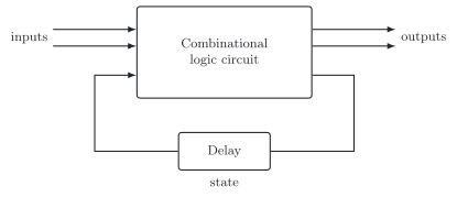
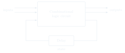
A sequential circuit (German: Schaltwerk) behaves differently: its output depends not only on the instantaneous values of its inputs, but also on past ones [5, p. 211], [12, p. 71]. A sequential circuit can therefore store information [12, p. 71]. Fricke describes its structure (figure): a combinational logic circuit with at least one output fed back to its inputs, with a delay in this feedback (German: Rückkopplung); the values that are fed back form the state (German: Zustand) of the circuit [12, p. 71].
You meet both types every day. In your smartphone, the logic that switches the display of chapter 1 and the logic of the ringtone of DET-03 are combinational logic circuits: whether the display is on and whether the phone rings follow from the inputs of the moment. The notice of a missed call, in contrast, stays until you have looked at it, and a step counter remembers every step so far – both are sequential circuits. The heat pump contains both as well. In the simplified rule of chapter 3, whether its compressor may start depends only on the six signals at this moment, a task for a combinational logic circuit; the same holds for the collective fault of DET-02, 3.4, which is 1 as long as any fault bit is 1. The number of compressor starts – 8 003 in DET-01, 9.1 – depends on everything that has happened before; a counter that counts the starts is a sequential circuit, and so is a fault message that stays stored until someone acknowledges it.
Combinational logic circuit
Sequential circuit
Output depends on
the present inputs only
the present and the past inputs
Information
not stored
stored as its state
Structure
gates without feedback
combinational logic circuit with feedback
Smartphone
display logic, ringtone logic
notice of a missed call, step counter
Heat pump
release logic, collective fault
counter of the compressor starts, fault message
The storage elements of sequential circuits, latches and flip-flops, follow in DET-06, counters in DET-08 and finite state machines in DET-09.
5.2 When a short pulse leaves a mark
A hazard lasts a few nanoseconds and then disappears. If the output drives something slow, it does no harm: nobody sees 9 ns on the display, and a relay, which needs milliseconds to switch, does not react to it at all. According to Lou and Yang, a spurious pulse in a combinational logic circuit usually does no serious harm, because it disappears quickly; it becomes dangerous when it reaches a sequential circuit such as a flip-flop and changes its state [9, p. 132]. Donzellini and his co-authors, too, consider it necessary to eliminate hazards only where they do harm, typically in sequential circuits without a clock [17, p. 70].
Our heat pump shows what this means. Suppose its counter counted every change of the release signal from 0 to 1 as a compressor start. A static 1 hazard at the release – a dip from 1 to 0 and back to 1 – would then be counted as a start that never happened, and the counter would show one start too many from then on. In our release logic of chapter 3, each signal appears only as it is or only negated, so the change of a single input cannot cause a logic hazard there [12, p. 67], [9, p. 131]. But if, for example, without a block and without a heating demand, the hot-water demand ended at the very moment when frost protection began, a function hazard could cause exactly such a dip.
The robot vacuum of the second guiding question suffers from the same kind of error. If a short pulse reaches the reset input of its Wi-Fi module, the module restarts and has to rebuild its connection to the router: the connection drops, even in the middle of the night, when the robot stands still in its dock.
Image by Qwen-Image 2.1
Where a short pulse can reach an input that reacts at any moment, such as an input of a sequential circuit without a clock or a clock signal itself, logic hazards must be avoided [18, p. 135]. In sequential circuits with a clock, which read their signals only at fixed moments, hazards can be tolerated [17, p. 70].
6 What have you learnt? – Summary and answers to the guiding questions
6.1 The building blocks of knowledge
Prime implicants: An implicant is a product term that implies the function; a prime implicant is an implicant that cannot be enlarged. Essential prime implicants cover a one that no other prime implicant covers and belong to every minimal disjunctive normal form (DNF); redundant ones can be left out. If ones remain, a selection of the other prime implicants completes the minimal DNF, which is then not always unique.
Quine–McCluskey algorithm: It writes the minterms as codes and sorts them into groups by the number of their ones. In part 1, it unites terms of consecutive groups that differ in one position, table by table, until the prime implicants remain; in part 2, the prime implicant chart selects the essential ones and, if needed, a few more. Its effort grows exponentially with the number of inputs; for large functions, software uses heuristic methods such as the Espresso heuristic logic minimizer.
Hazard analysis: Different delays let the output stumble while the inputs change: static 1 hazards, static 0 hazards and dynamic hazards. In a two-level circuit, a logic hazard, caused by the change of a single input, shows up as two neighbouring ones in different loops, and a redundant prime implicant removes it. A function hazard, caused by several inputs that change at once, cannot be removed by an additional term.
Combinational logic circuits and sequential circuits: The output of a combinational logic circuit depends only on its present inputs; a sequential circuit also depends on past inputs and stores information. A hazard does harm above all where a sequential circuit takes it in.
With these building blocks, you minimize a function by table instead of by eye, and you find out whether the minimal circuit also switches cleanly while its inputs change.
6.2 Answers to the guiding questions
Can a computer minimize a circuit for you – and how does it go about it?
Yes. The Quine–McCluskey algorithm needs no picture, only fixed rules: it writes the minterms as codes, unites terms that differ in one position, table by table, until the prime implicants remain, and then selects the fewest of them that cover all ones in the prime implicant chart. For the display, it finds the same three product terms as the Karnaugh map. Because its effort grows exponentially with the number of inputs, minimization software uses heuristic methods such as the Espresso heuristic logic minimizer for large functions.
Why does a cheap robot vacuum drop its Wi-Fi connection in the middle of the night?
Because of a hazard. When signals change, different delays can produce a short pulse that should not be there. If such a pulse reaches a circuit that remembers, such as the reset of the Wi-Fi module, the module restarts and has to reconnect. A circuit avoids this by removing its logic hazards with redundant prime implicants or by reading its signals only at fixed moments.
Six signals decide whether a heat pump may start: what do you do when a Karnaugh map becomes too large?
You leave the work to the algorithm. With six inputs, the map has 64 cells and is hard to read without mistakes. The algorithm treats the combinations that never occur as don’t cares, unites the 31 ones and the 16 don’t cares in six tables and leaves three essential prime implicants: Y=F+B⋅D+A⋅C⋅D⋅E. Here, as for even more inputs, a computer program does the work.
Where do I look things up? – Sources and references
All sources that I cite in this script with a number in square brackets, such as [5], are listed on the page References. There you will also find the books that I recommend for looking things up, the image licences and a note on the use of AI.