In our example system, the controller of the heat pump starts a hot-water charging when the temperature of the hot water falls 5 K below its set point. The hot-water programme switches between comfort times with a set point of 52.5 °C and eco times with a set point of 47.5 °C, so a charging starts below 47.5 °C in the comfort time and below 42.5 °C in the eco time. From Monday to Thursday, the comfort time ends at 23:00. During a block by the energy supplier, the heat pump must not start. In simplified form, the inputs and the output are:
A: the comfort time of the hot-water programme is active
B: the hot water is below 47.5 °C
C: the hot water is below 42.5 °C
D: the energy supplier blocks the heat pump
Y: a hot-water charging may start
a) Set up the truth table of Y with A as the input with the highest weight. In the rows that never occur, mark the output as a don’t care.
b) Minimize Y with the Quine–McCluskey algorithm, using the don’t cares.
c) A colleague builds the circuit directly from the description, as a two-level circuit with inverters for A and D: Ydirect=A⋅B⋅D+A⋅C⋅D. On a Thursday at 23:00, the comfort time ends, while the hot water is below 42.5 °C and there is no block. Show that the output of this circuit can drop to 0 for a moment.
d) Suppose a counter counts every rise of the output from 0 to 1 as the start of a hot-water charging. What does the dip of c) do to the counter? Is the counter a combinational logic circuit or a sequential circuit?
e) Can the output of your minimal circuit from b) drop to 0 at 23:00 as well? Give a reason.
the inputs A (‘comfort time active’), B (‘hot water below 47.5 °C’), C (‘hot water below 42.5 °C’) and D (‘block by the energy supplier’), and the output Y (‘hot-water charging may start’)
the rule: without a block, a charging starts below 47.5 °C in the comfort time and below 42.5 °C in the eco time; during a block, the heat pump must not start
c) the circuit of the colleague, Ydirect=A⋅B⋅D+A⋅C⋅D, with inverters for A and D; at 23:00, A falls from 1 to 0, while B=1, C=1 and D=0
d) a counter that counts every rise of the output from 0 to 1
Known:
From the description to the truth table (DET-03); don’t cares (DET-03)
Quine–McCluskey algorithm, part 1 (DET-04) and part 2 (DET-04); don’t cares count as ones while uniting and get no column in the chart (DET-04)
Two neighbouring ones in different loops as the mark of a logic hazard (DET-04); a variable that appears as it is and negated (DET-04)
A sequential circuit takes in a short pulse (DET-04)
Required
a) the truth table of Y with don’t cares
b) the minimized Y
c) the proof that the output of Ydirect can drop to 0 for a moment at 23:00
d) the effect of the dip on the counter, and the type of the counter
e) whether the minimal circuit can drop to 0 at 23:00, with a reason
a) Truth table
Water below 42.5 °C is always below 47.5 °C as well. The combination B=0 and C=1 therefore never occurs, and the output of the rows 2, 3, 10 and 11 is a don’t care, X (DET-03, 4.4). During a block, D=1, the output is 0 in all other rows. Without a block, a charging may start in the eco time, A=0, if the water is below 42.5 °C: row 6. In the comfort time, A=1, it may start if the water is below 47.5 °C: rows 12 and 14 (DET-03, 1.2):
Row
A
B
C
D
Y
0
0
0
0
0
0
1
0
0
0
1
0
2
0
0
1
0
X
3
0
0
1
1
X
4
0
1
0
0
0
5
0
1
0
1
0
6
0
1
1
0
1
7
0
1
1
1
0
8
1
0
0
0
0
9
1
0
0
1
0
10
1
0
1
0
X
11
1
0
1
1
X
12
1
1
0
0
1
13
1
1
0
1
0
14
1
1
1
0
1
15
1
1
1
1
0
Y(A,B,C,D)=∑m(6,12,14)+d(2,3,10,11)
Check by counting: of the 16 rows, 4 are don’t cares and 3 contain a 1, so 16−4−3=9 rows contain a 0 ✓
b) Minimization
Don’t cares count as ones while terms are united (DET-04, 3.2). The first table therefore holds the three minterms of the ones and the four don’t cares:
Group
Minterm
A
B
C
D
Ticked
1
2
0
0
1
0
✓
2
3
0
0
1
1
✓
2
6
0
1
1
0
✓
2
10
1
0
1
0
✓
2
12
1
1
0
0
✓
3
11
1
0
1
1
✓
3
14
1
1
1
0
✓
Comparing consecutive groups yields eight pairs (DET-04, 2.2):
Group
Minterms
A
B
C
D
Ticked
1
2, 3
0
0
1
-
✓
1
2, 6
0
-
1
0
✓
1
2, 10
-
0
1
0
✓
2
3, 11
-
0
1
1
✓
2
6, 14
-
1
1
0
✓
2
10, 11
1
0
1
-
✓
2
10, 14
1
-
1
0
✓
2
12, 14
1
1
-
0
Seven of them unite into two terms with four minterms each; the pair 11-0 (12, 14) finds no partner and remains without a tick:
Group
Minterms
A
B
C
D
Ticked
1
2, 3, 10, 11
-
0
1
-
1
2, 6, 10, 14
-
-
1
0
The prime implicants are the terms without a tick: A⋅B⋅D (12, 14), B⋅C (2, 3, 10, 11) and C⋅D (2, 6, 10, 14). B⋅C contains only don’t cares, the four combinations that never occur; it has nothing to cover and gets no row in the chart, which has a column for each of the three ones (DET-04, 2.3):
Prime implicant
6
12
14
C⋅D
●
●
A⋅B⋅D
●
●
Column 6 has a single mark in the row of C⋅D, column 12 in the row of A⋅B⋅D: both prime implicants are essential, and together they cover all three ones:
Y=C⋅D+A⋅B⋅D
Read: a hot-water charging may start without a block if the water is below 42.5 °C, whatever the time, or in the comfort time if it is below 47.5 °C.
Check with the truth table: C⋅D is 1 in rows 2, 6, 10 and 14, A⋅B⋅D in rows 12 and 14. Together, they cover the three ones 6, 12 and 14 and, besides, the rows 2 and 10, which are don’t cares, but no row with a 0 ✓
c) The circuit of the colleague
The circuit of the colleague fulfils the description: Ydirect is 1 in rows 2, 6, 12 and 14, that is, in the three ones and in row 2, a don’t care. But A appears in it as it is, in A⋅B⋅D, and negated, in A⋅C⋅D (DET-04, 4.3). At 23:00, the other inputs reduce both terms to this variable. For B=1, C=1 and D=0:
Ydirect=A⋅B⋅D+A⋅C⋅D=A⋅1⋅0+A⋅1⋅0=A+A
In theory, the output stays 1. But when A falls from 1 to 0, the term A⋅B⋅D falls as soon as its AND gate has followed, while A⋅C⋅D rises only after the inverter of A and its AND gate (DET-04, 4.2). For a moment, both inputs of the OR gate are 0, and the output drops to 0: a static 1 hazard. The change leads from minterm 14 (1110) to minterm 6 (0110); in the circuit of the colleague, minterm 14 lies only in A⋅B⋅D and minterm 6 only in A⋅C⋅D, so no term covers both.
d) The counter
During the dip, the output falls from 1 to 0 and rises back to 1. The counter sees this rise and counts it as the start of a hot-water charging, although no new charging has started. From then on, it shows one start too many.
The counter is a sequential circuit: its value depends on all rises so far, so it stores information as its state. A short pulse that it takes in leaves a lasting mark (DET-04, 5.2). A slow load would not react to the dip at all; the counter does, because it reacts to every rise.
e) The minimal circuit
In the minimal DNF Y=C⋅D+A⋅B⋅D, A appears only as it is, and no other variable appears both as it is and negated. The change of a single input therefore cannot cause a logic hazard (DET-04, 4.3). At 23:00, the term C⋅D does not depend on A and stays 1. For B=1, C=1 and D=0:
Y=C⋅D+A⋅B⋅D=1⋅0+A⋅1⋅0=1+A=1
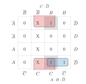
Check with the map of Y(A,B,C,D)=∑m(6,12,14)+d(2,3,10,11) (figure): the cells of minterms 14 and 6, before and after 23:00, are neighbours across the top and the bottom edge, and both lie in the loop C⋅D ✓
So no: the output of the minimal circuit cannot drop to 0 at 23:00. The term A⋅C⋅D of the colleague is not a prime implicant: it lies in the larger loop C⋅D, which contains both cells.
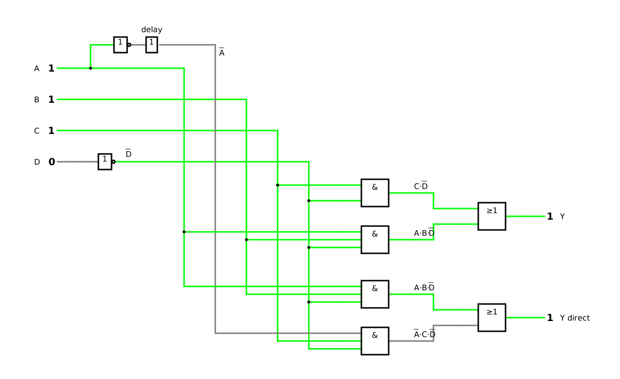
The simulation shows both circuits, driven by the same four inputs: the minimal circuit with the output Y above, the circuit of the colleague with the output Y direct below. A delay element behind the inverter of A enlarges its delay so much that you can watch the effect, as in the lesson (DET-04, 4.2). The simulation starts in the comfort time with water below 42.5 °C and without a block. Switch A from 1 to 0: the output of the colleague’s circuit drops to 0 for a moment, while the output of the minimal circuit stays 1. Without the delay element, the dip lasts only 5 µs in the simulation.