Your smartphone can vibrate when a call comes in. Two settings decide when: one for silent mode and one for ring mode. On an iPhone, for example, a single setting with four options covers both: Always Play, Play in Silent Mode, Don’t Play in Silent Mode and Never Play. The phone vibrates for an incoming call in silent mode if vibration is switched on for silent mode, and in ring mode if vibration is switched on for ring mode. The inputs and the output are:
A: a call is coming in
B: silent mode is on; otherwise, the phone is in ring mode
C: vibration is switched on for silent mode
D: vibration is switched on for ring mode
Y: the vibration motor runs
a) Set up the truth table of Y with A as the input with the highest weight, and give its minterm list.
b) Minimize Y with the Quine–McCluskey algorithm.
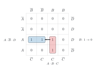
c) While a call is coming in, you switch the phone from silent mode back to ring mode, and vibration is switched on for both modes. Can the output Y of the two-level circuit of your result from b) drop to 0 for a moment? Give a reason with the Karnaugh map.
d) Make the circuit free of this hazard, and draw it according to the standard of the International Electrotechnical Commission (IEC), IEC 60617.
the inputs A (‘call coming in’), B (‘silent mode on’), C (‘vibration on for silent mode’) and D (‘vibration on for ring mode’), and the output Y (‘vibration motor runs’)
the rule: during an incoming call, the phone vibrates in silent mode if vibration is on for silent mode, and in ring mode if vibration is on for ring mode
c) the change from silent mode to ring mode during an incoming call, with vibration on for both modes
Known:
From the description to the truth table (DET-03); minterm list (DET-03)
Quine–McCluskey algorithm: codes and groups (DET-04), part 1 (DET-04), part 2 with the prime implicant chart (DET-04)
Two neighbouring ones in different loops as the mark of a logic hazard (DET-04)
Hazard analysis and the redundant prime implicant that unites two loops (DET-04)
a) the truth table and the minterm list of Y
b) the minimized Y
c) whether Y can drop to 0 for a moment, with a reason
d) the hazard-free form and its circuit
a) Truth table
Without an incoming call, the motor stays off: a 0 in rows 0 to 7. During a call in silent mode, A=1 and B=1, the motor runs if vibration is on for silent mode, C=1: rows 14 and 15. During a call in ring mode, A=1 and B=0, it runs if vibration is on for ring mode, D=1: rows 9 and 11 (DET-03, 1.2):
Row
A
B
C
D
Y
0
0
0
0
0
0
1
0
0
0
1
0
2
0
0
1
0
0
3
0
0
1
1
0
4
0
1
0
0
0
5
0
1
0
1
0
6
0
1
1
0
0
7
0
1
1
1
0
8
1
0
0
0
0
9
1
0
0
1
1
10
1
0
1
0
0
11
1
0
1
1
1
12
1
1
0
0
0
13
1
1
0
1
0
14
1
1
1
0
1
15
1
1
1
1
1
The minterm list names the four rows with a 1 (DET-03, 2.5):
Y(A,B,C,D)=∑m(9,11,14,15)
Check by counting: of the eight rows with a call, four are in silent mode and four in ring mode. In each group of four, the motor runs in the two rows in which the setting of its mode is on, so the table has 2+2=4 ones ✓
b) Minimization
Part 1 sorts the codes of the four minterms into groups (DET-04, 2.1): 9 (1001) has two ones, 11 (1011) and 14 (1110) have three, and 15 (1111) has four. Comparing consecutive groups yields three pairs (DET-04, 2.2): 9 and 11 differ only in C, 11 and 15 only in B, and 14 and 15 only in D. All four minterms are ticked:
Group
Minterm
A
B
C
D
Ticked
2
9
1
0
0
1
✓
3
11
1
0
1
1
✓
3
14
1
1
1
0
✓
4
15
1
1
1
1
✓
The second table holds the three pairs:
Group
Minterms
A
B
C
D
Ticked
2
9, 11
1
0
-
1
3
11, 15
1
-
1
1
3
14, 15
1
1
1
-
No two pairs have their dashes in the same position, so part 1 ends. The three pairs are the prime implicants: 10-1 (9, 11), the term A⋅B⋅D; 1-11 (11, 15), the term A⋅C⋅D; and 111- (14, 15), the term A⋅B⋅C.
In the prime implicant chart (DET-04, 2.3), column 9 has a single mark in the row of A⋅B⋅D, column 14 a single mark in the row of A⋅B⋅C:
Prime implicant
9
11
14
15
A⋅B⋅C
●
●
A⋅B⋅D
●
●
A⋅C⋅D
●
●
Both prime implicants are essential, and together they cover all four minterms; A⋅C⋅D is not needed:
Y=A⋅B⋅C+A⋅B⋅D
Read: the motor runs during an incoming call in silent mode with vibration on for silent mode, or in ring mode with vibration on for ring mode – the rule of the task in two product terms.
Check with the minterm list: A⋅B⋅C is 1 in rows 14 and 15, A⋅B⋅D in rows 9 and 11; together, these are the four ones of Y ✓
c) Switching to ring mode
In the minimal DNF, B appears as it is in A⋅B⋅C and negated in A⋅B⋅D (DET-04, 4.3). During an incoming call with vibration on for both modes, both terms reduce to this variable. For A=1, C=1 and D=1:
Y=A⋅B⋅C+A⋅B⋅D=1⋅B⋅1+1⋅B⋅1=B+B
In the map (figure), switching from silent mode to ring mode, B from 1 to 0, leads from the cell of minterm 15 (1111) to the neighbouring cell of minterm 11 (1011). Both contain a one, but they lie in different loops, so a static 1 hazard can occur (DET-04, 4.2). The term A⋅B⋅C falls as soon as its AND gate has followed B, while A⋅B⋅D rises only after the inverter of B and its AND gate. For a moment, both inputs of the OR gate can be 0, and Y drops to 0. So yes: the output can drop to 0 for a moment.
d) Hazard-free circuit
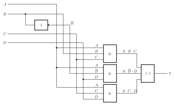
The redundant prime implicant A⋅C⋅D unites the two loops: it contains the cells of minterms 11 and 15 and does not depend on B (DET-04, 4.3). Added to the minimal DNF, it holds the output at 1 while B changes with A=1, C=1 and D=1, and it makes the circuit free of this hazard:
Y=A⋅B⋅C+A⋅B⋅D+A⋅C⋅D
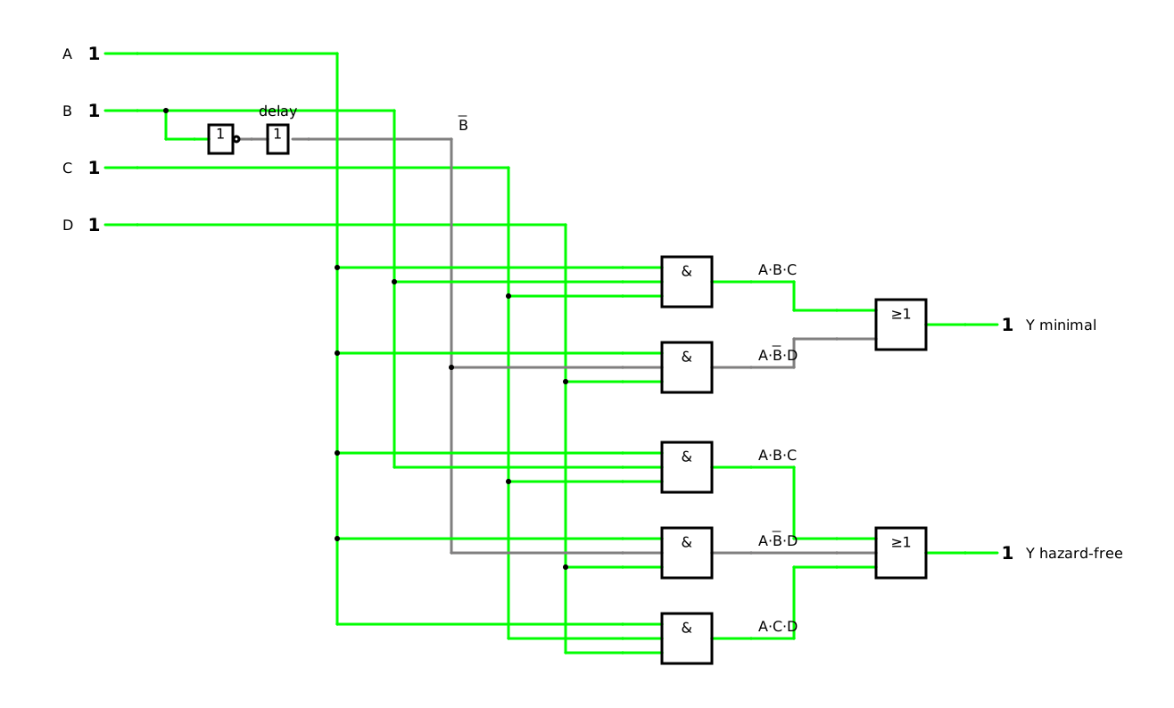
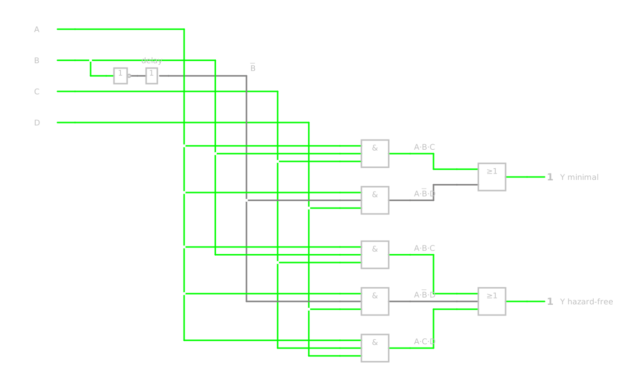
The two-level circuit (figure) needs an inverter for B, three AND gates with three inputs each and an OR gate with three inputs (DET-03, 5.1). Compared with the minimal circuit, the price is one more AND gate and a third input of the OR gate.
Check for A=1, C=1 and D=1:
A⋅C⋅D=1⋅1⋅1=1
The added term stays 1, whatever B does ✓
The simulation shows both circuits, driven by the same four inputs: the minimal circuit with the output Y minimal above, the hazard-free circuit with the output Y hazard-free below. A delay element behind the inverter of B enlarges its delay so much that you can watch the effect, as in the lesson (DET-04, 4.2). The simulation starts during a call in silent mode with vibration on for both modes. Switch B from 1 to 0: the output of the minimal circuit drops to 0 for a moment, while the output of the hazard-free circuit stays 1. Without the delay element, the dip lasts only 5 µs in the simulation.