
Prof. Dr. Thorsten Jungmann (last updated 2026-10-25)
Relates to DET-04 Algorithmic minimization of functions with many inputs and hazard analysis
Task
Different paths through a circuit have different delays. While the inputs change, the output of a circuit whose truth table is correct can therefore show short, unwanted pulses. In each function, the first variable has the highest weight.
a) Describe the situation in which a static 1 hazard can occur, and the situation in which a static 0 hazard can occur.
b) The function is built as a two-level circuit from its minimal disjunctive normal form (DNF), , with an inverter for . Find the change of a single input that can cause a static 1 hazard. Which values do the other inputs have?
c) Each gate, the inverter included, has a propagation delay of 10 ns. At , falls from 1 to 0, while the other inputs keep the values found in b). Draw the timing diagram of , , , and . How long does the dip last, and after what time has the output reached its final value for good?
d) Make the circuit of b) free of this hazard with an additional product term. Why is the circuit then no longer minimal?
e) The minimal DNF of is . Find all changes of a single input that can cause a static 1 hazard in its two-level circuit, and make the circuit free of them.
f) In the circuit , both inputs change at the same moment: from 1 to 0 and from 0 to 1. What can the output do? Can an additional term prevent it?
Solution
Given
Given explicitly:
- b) to d) with the minimal DNF , built as a two-level circuit with an inverter for
- c) a propagation delay of 10 ns for each gate, the inverter included; falls from 1 to 0 at
- e) with the minimal DNF
- f) ; falls from 1 to 0 and rises from 0 to 1 at the same moment
Known:
- Static 1 hazard, static 0 hazard and dynamic hazard (DET-04)
- The race between two paths; two neighbouring ones in different loops as the mark of a logic hazard in a two-level circuit (DET-04)
- Hazard analysis: a variable that appears as it is in one product term and negated in another; redundant prime implicants that unite the separate prime implicants (DET-04)
- Redundant prime implicants: all their ones lie in the essential prime implicants (DET-04)
- Function hazard: several inputs change at once (DET-04)
- Delays add up along each path; the delay of a circuit is the delay of its longest path (DET-02)
- Neighbours in the Karnaugh map, also across the edges (DET-03)
Required
a) the situations in which a static 1 hazard and a static 0 hazard can occur
b) the change of a single input that can cause a static 1 hazard in , with the values of the other inputs
c) the timing diagram, the duration of the dip and the time after which the output has reached its final value
d) the hazard-free form of and the reason why it is no longer minimal
e) all changes of a single input that can cause a static 1 hazard in , and the hazard-free form
f) what the output of can do, and whether an additional term can prevent it
a) Static 1 and static 0 hazards
Hazards are named after what the output should do (DET-04, 4.1). A static 1 hazard can occur when the inputs change from one combination for which the output is 1 to another combination for which the output is 1 as well. The output should stay 1, but because different paths have different delays, it drops to 0 for a moment.
A static 0 hazard can occur when the inputs change between two combinations for which the output is 0. The output should stay 0, but it rises to 1 for a moment.
b) Finding the hazard
In a two-level circuit, a logic hazard shows up as two neighbouring ones that do not lie in a common loop of the minimal DNF (DET-04, 4.2). It helps to look for a variable that appears as it is in one product term and negated in another (DET-04, 4.3). In , only does: negated in , as it is in . If the other variables are set so that both terms reduce to this variable, the expression becomes . For and :
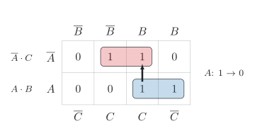
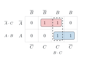
In theory, is always 1, but while changes, the output can be 0 for a moment. In the map (figure), the change of leads between the cell of minterm 7 (111) and the neighbouring cell of minterm 3 (011). Both cells contain a one, but they lie in different loops, and : a static 1 hazard can occur when changes while and .
c) Timing diagram
The output of the two-level circuit is
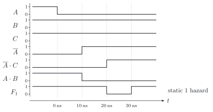
Follow the change through the circuit, gate by gate, as in the lesson (DET-04, 4.2), with and (figure):
- At , falls from 1 to 0.
- After 10 ns, the output of the AND gate for has followed and is 0; at the same time, the output of the inverter, , rises to 1.
- The AND gate for needs another 10 ns, so its output rises only after 20 ns.
- Between 10 ns and 20 ns, both inputs of the OR gate are 0. With its own delay, the output is 0 from 20 ns to 30 ns.
The dip lasts
The output has reached its final value for good when the change has passed the longest path of the circuit, from through the inverter, the AND gate for and the OR gate (DET-02, 6.3). This path has three gates:
So you have to wait for the delay of the longest path until all hazards have settled. When rises instead, becomes 1 after 10 ns, before becomes 0 after 20 ns, and with these delays, there is no dip.
Check by counting the gates on the two paths of to the output: the direct path through the AND gate for and the OR gate has two gates, , the time at which the dip begins; the path through the inverter has three, , the time at which it ends ✓
d) Removing the hazard
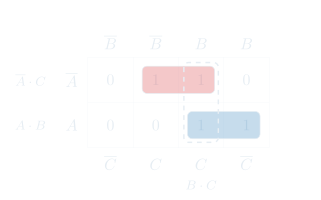
A redundant prime implicant that unites the two separate loops removes the hazard (DET-04, 4.3). The cells of minterms 3 and 7 form the loop (figure, dashed): there, and are 1, while changes. It is a prime implicant of , but a redundant one, because its ones already lie in and (DET-04, 1.2). Added to the minimal DNF, it makes the circuit free of this logic hazard:
While changes with and , the new term does not depend on and holds the output at 1, however the delays turn out. Check for and :
✓
The price is an additional AND gate with two inputs and a third input of the OR gate. The circuit needs more gates than its minimal DNF, so it is no longer minimal; it is the complete sum of all three prime implicants of .
e) Four inputs
In , all four variables appear both as they are and negated. A change of a single input can only lead from one term to another if the two terms differ in this variable alone (DET-04, 4.3):
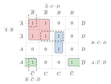
- is negated in and appears as it is in . With , and , both terms reduce to and . The change of leads between minterm 0 (0000) and minterm 8 (1000); in the map, these two cells are neighbours across the top and the bottom edge (DET-03, 4.1), and they lie in different loops.
- is negated in and appears as it is in . With , and , both terms reduce to and . The change of leads between minterm 3 (0011) and minterm 7 (0111), which lie in different loops.
- and appear as they are in and negated in . These two terms differ in both variables, so no change of a single input leads from one to the other.
For , and :
For , and :
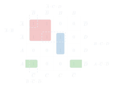
Two redundant prime implicants unite the separate loops (figure, dashed): with the cells of minterms 0 and 8, and with the cells of minterms 3 and 7. Added to the minimal DNF, they make the circuit free of logic hazards:
Check for the change of , with , and :
Check for the change of , with , and :
Both added terms stay 1, whatever the changing input does ✓
The two added terms are the remaining prime implicants of ; the hazard-free form is the complete sum of all five.
f) Two inputs at once
Here, two inputs change at the same moment, and their changes never arrive at exactly the same time. If falls before rises, the OR gate sees and for a moment:
Before and after the change, is 1, so the output drops to 0 for a moment: a static 1 hazard. Because it is caused by the change of several inputs, it is a function hazard (DET-04, 4.4). If rises first, the gate sees and for a moment, and the output stays 1.
No additional term can prevent the dip. On its way, the circuit passes through the combination , , for which the function itself demands . To hold the output at 1, a term would have to be 1 for exactly this combination, and it would change the function. The dip is avoided by reading the output only when all changes have settled, or by making sure that the inputs never change at the same time (DET-04, 4.4).