
Prof. Dr. Thorsten Jungmann (last updated 2025-09-03)
1 What does it look like?
A relay (German: Relais) is a small switching device in a housing that is usually rectangular or cuboid. From the outside, you can see the connecting contacts: on the one hand for the coil, on the other hand for the switching contacts. Relays can be transparent (for illustration and diagnosis) or optically closed. They can be integrated directly into electric circuits or be intended for installation on a mounting rail in the control cabinet.
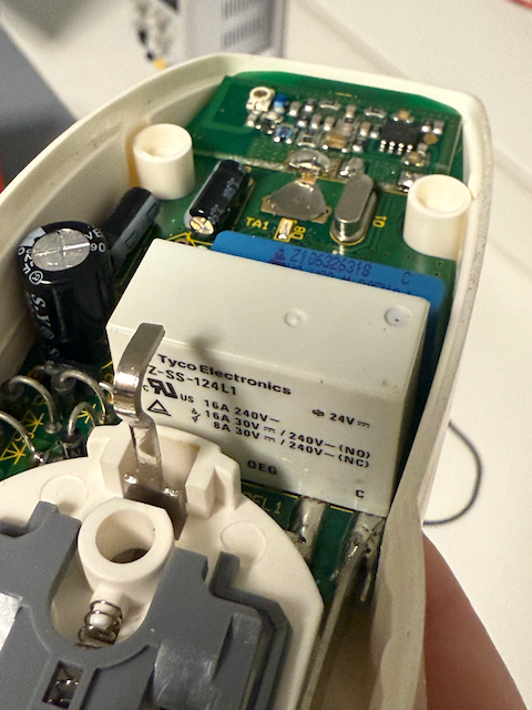
Relay in a switching socket-outlet
The relay (white cuboid with the inscription ‘Tyco Elektronics’) switches opens and closes the electric circuit in the radio-controlled switching socket-outlet shown.
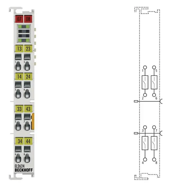
Relay terminal
The output terminal EL2624 from Beckhoff has four relays, each with a single contact. The relay contact can be used up to 125 V AC or 30 V DC. The signal state of the EtherCAT terminal is indicated by light emitting diodes. The EL2624 is equipped with potential-free contacts. The power contacts are passed through.
Source: Elektroshop Wagner
2 What can it do?
A relay switches electric circuits on or off electrically. It allows you to switch a larger load current with a small control current. Relays are used for galvanic isolation, signal amplification and the automation of electric circuits.
3 How does it work?
A relay uses a coil that generates a magnetic field when a voltage is applied. This magnetic field attracts a movable armature and actuates mechanical contacts. In this way, the load circuit can be closed or opened. The standard relay is monostable, i.e. it has one stable switching position (coil de-energized).
There are different types of relay:
- single-throw relays (normally open contact or normally closed contact),
- change-over relays (changing over),
- special forms such as time relays or bistable relays (two stable switching positions),
- relay terminals with a connection to a data bus as part of automation solutions.
4 What does it look like inside?
Inside are the coil, an iron core, a movable armature and the switching contacts. When current flows through the coil, the magnetic core attracts the armature and thereby moves the contacts. The contacts are usually reset by a spring. Some relays have an integrated freewheeling diode. It short-circuits the flyback voltage that arises after switch-off as the magnetic field decays, and protects the connected electric circuit from the energy that would otherwise discharge into the electric circuit and could damage sensitive components.
5 What role does it play in teaching?
The relay is a vivid example of the relationship between electrical energy, magnetism and mechanical motion. It shows the practical application of the coil in the control circuit and the load circuit. In teaching, it illustrates the principle of galvanic isolation and of controlling high currents by means of small control currents. It also lends itself as a starting point for the dimensioning of freewheeling diodes.
6 What role does it play in practice?
Relays are widely used in control and automation engineering, in vehicles, in household appliances and in industrial control cabinets. They are used when signals are to be amplified or galvanically isolated, or when small and medium loads are to be switched reliably. For large loads, contactors are used.
Even though many applications have now been replaced by semiconductors, relays are still of great importance because of their robustness and their clear switching function.
There are also relays with integrated additional functions such as on-delay and off-delay (bathroom fan) or a timer stage (staircase lighting).
Symbols
- Letter code in schematics: K
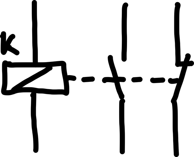
Example: relay with two switching contacts
Calculations
- Power consumption in operation
- Dimensioning of the freewheeling diode
With regard to the contacts:
- max. inrush current
- max. continuous current
- max. breaking current