Prof. Dr. Thorsten Jungmann (last updated 2026-10-20)
Overview of this lesson
What is this lesson about? – The guiding questions:
What awaits you in this module, and how will you show at the end what you can do?
Why is 1 + 1 = 10 not a mistake?
How can a heat pump that knows only two states, on and off, show the time 23:59, count 8 003 compressor starts and store an outside temperature of −7 °C?
What will you be able to do at the end of this lesson? – The intended learning outcomes:
You know how the module is organized and what is expected of you.
You understand how analogue and digital signals are related.
You convert numbers between positional number systems.
You represent signed numbers.
You carry out binary arithmetic.
What will you know at the end of this lesson? – The building blocks of knowledge:
1 Studying successfully – Nothing comes from nothing!
1.1 What does ‘studying’ mean?
Welcome to Digital Electronics! You are in your third semester and already know a good deal about studying. Nevertheless, I would like to begin this module with the person who decides its success: you.
What does ‘studying’ mean?
Studere (Latin): to strive for something, to pursue something, to devote oneself intensively to a matter on one’s own initiative, to engage in something scientifically, to learn.
Where does success come from? From your behaviour during your studies!
Take an active part in the classes: listen attentively, take notes, ask questions, discuss and join in the exercises.
Prepare for each class and follow it up.
Practise applying the methods you have learned. Digital electronics is learned by doing, not by watching.
Learn, work and sometimes celebrate together as a group.
Draw on solid prior knowledge and refresh it if necessary.
Keep the goals in sight from the very beginning.
Every lesson in this script helps you with the last point. It begins with an overview of the guiding questions, the intended learning outcomes and the building blocks of knowledge, and its main part ends with a summary and the answers to the guiding questions. Read the overview before the class, and check afterwards whether you can answer the guiding questions yourself.
NOW:
Set up a notebook for this module and take notes, for example in the Cornell note-taking format. Cornell-note.pdf
2 What does the module build on? – Necessary prior knowledge
2.1 What you bring with you
Formally, Digital Electronics requires nothing: the module description names no prerequisites. In terms of content, however, I build on knowledge that you bring with you from school and from your first semesters:
From mathematics: powers such as 210, the place value of the digits in a number and written addition and subtraction.
From physics and the fundamentals of electrical engineering: voltage as a quantity, because every 0 and every 1 in a circuit is represented by a voltage.
From English: the module is taught in English. Each technical term is introduced together with its German equivalent, so that you can also read German datasheets and textbooks.
Digital electronics is a subject in which each new topic builds directly on the previous one. Number systems lead to logic operations, logic operations to circuits, and circuits to counters and controllers. If you miss a step, the next one becomes difficult. So it pays to keep up from the very first session.
Important!
Look at the detail pages on prior knowledge to see what exactly is expected. If you notice gaps there, close them very soon – before they become a problem in the exercises.
FOLLOW-UP of today's lesson:
Question your prior knowledge, especially of powers of two, and refresh it if necessary.
3 How do I teach? – Didactic principles of my courses
3.1 How a session works
Our module consists of twelve sessions, each on a Tuesday from 16:00 to 19:00, and every session has two parts. First, I introduce the new content in a lecture. The slides structure the content and illustrate it, and this script contains everything in full, so that you can read up on it at any time – even if you have missed a session. Ideally, you read the script in preparation for each session; then the lecture is not your first encounter with the content. Exercises follow, in which you first solve the tasks on your own; after that, I present the solution, and we discuss it.
Studying at university differs from school in one respect: the principle is not ‘only what has been taught is relevant in the examination’. What you must be able to do at the end is set out in the module description, and my courses follow it. They work like this:
I show and explain once how it works.
I demonstrate it with an example.
I answer questions about the procedure so that nothing remains unclear. If a question concerns prior knowledge from school or something that I explained in an earlier session, I refer you to the script and to your fellow students.
I give you exercises to practise what has been explained, and I support you while you work on them.
I give you model solutions, so that you can compare them with your own.
For further practice, I tell you where to find additional exercises – above all in the textbook.
This may sound harsh at first, but in my view it reflects the principle of studying at university: you take responsibility for your own learning.
3.2 Like at a buffet – learning under your own responsibility
At university, you yourself are responsible for your learning success. You act; you get what you need. An old piece of wisdom among teachers puts it in a nutshell:
Ralph W. Tyler, 1949
‘Learning takes place through the active behavior of the student; it is what he does that he learns, not what the teacher does.’ [6, p. 63]
Students learn from what they do themselves. That is why my courses are like a buffet: instead of ‘all you can eat’, the offer comprises ‘more than you can eat’.
Image by Qwen-Image 2.1
The analogy to my courses:
I cook tasty dishes from fresh ingredients.
I arrange them as appealingly as I can and present them transparently, so that everyone knows what they are.
For unfamiliar dishes, I show how to handle and eat them.
After that, it is up to the guests to help themselves – and to ask when something is missing or unclear.
It is entirely the guests’ responsibility, not mine, to take the right dishes in the right amount and in the right order, so that they can digest them – not too much and not too little.
Not only at the buffet but also in class, it helps to discover something familiar, so that you do not feel lost. That is why two examples accompany us through all sessions: the smartphone and the heat pump.
3.3 Everyday example: the smartphone
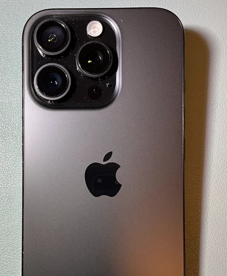
You carry a digital system with you every day: your smartphone. In every lesson, it is the first example with which I connect the new topic to something familiar.
A processor and memory that work exclusively with 0 and 1
Sensors and converters that turn sound, light, touch and the battery voltage into numbers – and numbers back into sound and light
Every photo, every message and every song stored as a sequence of 0s and 1s
Already in this lesson, the smartphone provides three examples: its battery level as a binary number, the colours of its display as hexadecimal numbers and its microphone and loudspeaker, where the analogue and the digital world meet. In the course of the semester, we will meet it again and again: as an example of logic operations, of memories and counters and of the signal path from the touch on the display to the vibration. Take a look at your own smartphone while you read: almost everything you see and hear on it has passed through digital circuits.
3.4 Industrial example: the heat pump
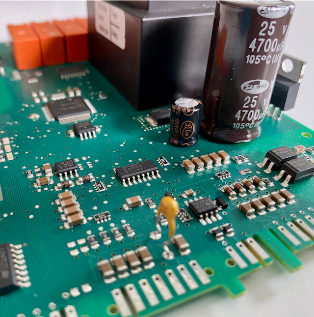
After the smartphone, each lesson turns to an example of a mechatronic system: the control of an air-to-water heat pump. It is a real system – a Stiebel Eltron WPL 24 A heat pump with the controller WPMsystem – whose values we can read at any time. Its heart is a control board.
A heat pump is a typical mechatronic system: sensors measure temperatures and pressures, a controller decides, and actuators – compressor, pumps and valves – carry out its decisions.
The obvious:
The heat pump with fan and compressor
The controller, whose values – temperatures, time and date, counter readings – can be read in a web browser via the Internet Service Gateway (ISG)
The hidden:
A control board with a microcontroller that evaluates sensors and switches pumps and valves via relays
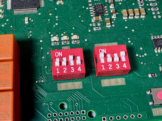
Dual in-line package (DIP) switches with which the board is configured
Communication over a Controller Area Network (CAN) bus
All values – the time, the number of compressor starts, the temperatures – stored and processed as binary numbers
In this lesson, the heat pump provides the time 23:59, the 8 003 compressor starts and the temperatures −7 °C and −20 °C as examples. The exercises of the coming weeks rebuild functions of this system as digital circuits; on the real board, the microcontroller takes over this logic. You will find more details on the detail page on the control board.
3.5 The logic simulator
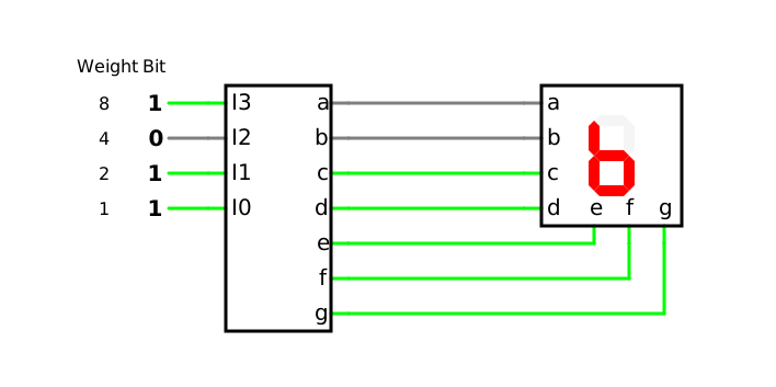
Some things cannot be seen, even on an open circuit board: which signal is 0 and which is 1 at a given moment. A simulator makes the invisible visible. For this module, I provide the logic simulator CircuitJS at sim.wattsinside.eu; you log in with the login details that I give you in class.
In the example, four switches set a binary number, and a 7-segment display decoder turns it into the matching digit on the display. Click on a switch, and you see at once how the digit changes. The decoder shows not only the digits 0 to 9 but also the letters A to F, which you will meet as hexadecimal digits in chapter 6.
How you work with the simulator:
The link below a simulation opens the simulator in a new tab, with the circuit already loaded.
You can change the circuit, for example switch an input or add a gate.
Below each simulation in this script, a collapsed box contains the circuit as text. With File → Import From Text… you load it into the simulator; with File → Export As Text… you take your changed version with you.
I use the simulator again and again in the lectures and in the exercises, because it lets you follow step by step what happens in a circuit. You can use it yourself whenever you want to try something out – a simulated circuit cannot be damaged.
3.6 The textbook
This script contains everything you need for this module. For anyone who wants a second explanation or more practice, most topics can also be found in the textbook by Brock J. LaMeres [5]. It explains the topics step by step and contains many worked examples and, at the end of each chapter, a large number of exercises – ideal for further practice.
Introduction to Logic Circuits & Logic Design with VHDL
Brock J. LaMeres
3rd edition, Springer, Cham, 2024
ISBN 978-3-031-42547-9
The HSBI library offers the book as an electronic full text on Springer Link: link to the book. Access works in the university network, including Wi-Fi, and from outside via a virtual private network (VPN). On his YouTube channel Digital Logic & Programming, the author explains most sections of the book in a video of their own.
Use the book as a second explanation: if a topic in the script is not clear to you, read the corresponding section there – a different perspective often helps. With the concept checks at the end of each section, you can test your understanding.
Other textbooks will do as well; you will find a selection on the page References.
How do I get books for my studies?
Library
borrow
scan from the course reserve
obtain via interlibrary loan
suggest a purchase
Bookshop
buy
4 The examination – your stage
4.1 The eAssessment
At the end of the semester, I prepare a stage for you on which you can show what you can do. Stage fright is okay, but exam anxiety should not arise – it is all a matter of practice!
Image by Qwen-Image 2.1
Location and duration: ILIAS eAssessment in the computer room on the Gütersloh campus, 60 minutes.
Procedure on the day of the examination:
Be in the examination room in good time. Switch off your mobile devices – smartphone, tablet, smartwatch – and put them at the front of the room.
Have your student ID ready for the identity check.
Log in to the eAssessment server with your HSBI login details. I give you the password with which you start the examination.
The time starts when you click ‘Start test’. Throughout the examination, I am available for clarifying questions about the tasks; please understand that I do not give individual help with solving them.
Stay in your seat until I announce the end of the examination time.
Registration: Make sure that you are registered for the examination in the LSF. The examination period on the Gütersloh campus runs from 2 to 9 January 2027; the date of the examination is in the examination schedule.
Aid: your own non-programmable calculator of the Casio FX-82 series.
By the next class:
Get yourself a calculator of the Casio FX-82 series, so that you can practise using it in the exercises.
In the last session, DET-12 on 22 December 2026, we hold a mock exam (German: Probeklausur) in computer room G105 on the Gütersloh campus – under examination conditions and with a discussion afterwards. There you get to know the eAssessment system and my style of questions, and you can assess your learning progress. Treat it like a dress rehearsal: the more seriously you take it, the more relaxed you will be on the big day.
5 What is this module about? – Introduction to digital electronics
5.1 Analogue and digital
Digital systems have found their way into almost every area of our lives – from the smartphone and the car to the household appliance and the heat pump. To understand why, we start with what distinguishes a digital system from its counterpart, the analogue system [5].
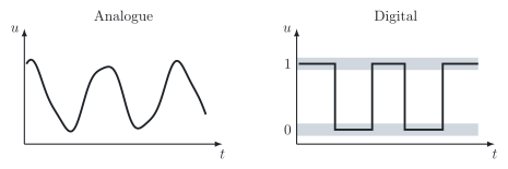
In electrical systems, signals (German: Signale) transmit information by means of an electrical quantity, usually a voltage. An analogue signal (German: analoges Signal) changes continuously over time, and its value maps the information directly. A microphone, for example, delivers a voltage that follows the sound pressure: the louder the sound, the larger the voltage.
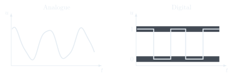
In a digital signal (German: digitales Signal), the electrical signal is not the information itself; it carries an encoded form of it, most commonly in binary, with the two values 0 and 1. Each of them is assigned a range of the voltage: in the lower range, the signal stands for 0; in the upper range, for 1. Between the two ranges lies a gap, which the signal passes through only while it switches. Only these two values matter, so the signal is discrete rather than continuous. In the simplest model, the gap shrinks to a single threshold (German: Schwelle) in the middle of the voltage range: above it, the signal stands for 1, below it for 0.
In your smartphone, both worlds meet. The sound in your earbuds and the voltage of the rechargeable battery are analogue; the music file in the memory and the data transmitted over the mobile network are digital. Analogue-to-digital (A/D) and digital-to-analogue (D/A) conversion link both worlds, turning analogue signals into rows of 0s and 1s and vice versa.
5.2 Why digital?
Why have digital systems replaced analogue ones wherever possible? LaMeres names three reasons [5, pp. 3–4]:
Noise immunity (German: Störfestigkeit): Every signal picks up electrical noise on its way. In an analogue signal, the noise becomes part of the information – you hear it as crackling in a radio. A digital signal tolerates a considerable amount of noise: as long as the noise does not push the voltage out of its range, a 0 remains a 0 and a 1 remains a 1. Once the receiver has recognized the value, the noise is gone.
Simple circuits: To produce a 0 or a 1, a switch is enough – it connects the output either to a low or to a high voltage. Such switches are easy to build from transistors: a digital circuit that inverts a signal needs only two of them, whereas an analogue amplifier needs dozens to map its input faithfully to its output despite variations in temperature and in the voltage it is supplied with.
Low power consumption: Digital circuits in complementary metal oxide semiconductor (CMOS) technology need hardly any power to keep a switch on or off. This is why your smartphone can run a powerful computer on a rechargeable battery.
Lou and Yang add further benefits [9, p. 4]. The same noise immunity lets a digital system store data and read it back without degradation, whereas ageing and wear degrade information stored in analogue form. And a digital system controlled by software is programmable: it gains new functions without new hardware – your smartphone does so with every software update.
Digital electronics also brings challenges. Two of them accompany us in this module:
Converters: At the transition between the physical world and the electrical world, analogue technology will always be needed [5, p. 4]: microphones, cameras, sensors and displays work with analogue quantities. Converters build the bridge, and every digital value is only an approximation of the analogue one; the difference is the quantization error (German: Quantisierungsfehler) [9, p. 411]. Chapter 10 takes a first look at this border.
Timing: Real signals never change at exactly the same moment. In a circuit, this can cause short, unwanted pulses at the output, called hazards (German: Hazards) [5, p. 142]. You will learn in DET-04 how to recognize and avoid them.
5.3 Our leading character: the bit
In the script for Electrical Engineering 1, the leading character is the electron. In Digital Electronics, it is the bit (German: Bit), short for binary digit; the term was made popular by the information theory of Shannon in 1948. A bit is the smallest unit of information: it takes one of two values, 0 or 1 – yes or no, on or off.
In a circuit, a bit is a voltage, and its logic level (German: Logikpegel) states in which of two voltage ranges it lies: in the upper range, it is called HIGH, in the lower range LOW; in the simplest model, a threshold separates the two [5, p. 51]. In positive logic (German: positive Logik), which we use in this module, HIGH stands for 1 and LOW for 0.
Which voltages these are depends on the supply voltage (German: Versorgungsspannung) and the logic family (German: Logikfamilie) of a circuit [5, pp. 54, 63]. The supply voltage sets the range of all signals, from 0 V upwards. A logic family is a series of circuits in the same technology; its name often states its supply voltage, as in +3.3 V CMOS [5, p. 63].
The classic 7400 family in transistor–transistor logic (TTL, German: Transistor-Transistor-Logik) is supplied with 5 V [5, p. 73]; its HIGH lies below 5 V, because the output is not pulled fully up to the supply voltage [5, p. 72]. In CMOS technology, HIGH lies close to the supply voltage [5, p. 62]. The classic 4000 series of CMOS works with 3 V to 18 V [11]; modern CMOS circuits, including most microcontrollers, typically work with 1.8 V, 3.3 V or 5 V:
Logic family
Technology
Supply voltage
7400 series (classic)
TTL
5 V
4000 series (classic)
CMOS
3 V to 18 V
74HC series
CMOS
2 V to 6 V
74HCT series, TTL-compatible inputs
CMOS
4.5 V to 5.5 V
74LVC series
CMOS
1.65 V to 3.6 V
Our simulator works with 5 V and ideal levels: a logic input supplies 5 V for a 1 and 0 V for a 0, and a logic output shows a 1 from 2.5 V upwards.
With several bits, the possibilities multiply: two bits give four combinations, three bits eight and, in general, n bits give 2n combinations. This is how a heat pump that knows only two states, on and off, can store times, counter readings and temperatures.
5.4 The module at a glance
With the bit, we have the foundation on which everything else is built. In the coming weeks, the module leads you step by step from the single bit to programmable devices:
According to the module description, at the end of the module you will be able to:
analyse and design simple digital circuits and place them in the context of control engineering,
develop simple digital circuits that solve control tasks from various technical fields,
minimize logic functions with theoretical methods such as Boolean algebra and with algorithmic methods such as the Quine–McCluskey algorithm,
identify the benefits of digital systems for a given problem, develop solutions and justify and defend them,
explain the fundamentals of programmable logic devices and field-programmable gate arrays (FPGAs) and their description with hardware description languages.
The smartphone and the heat pump accompany us through all sessions. You will see that every topic of this module can be found in them – and that, in the end, everything comes down to the bit.
6 Counting with 0 and 1 – Positional number systems
6.1 Positional number systems
We think in decimal, whereas digital circuits work in binary. To build a bridge between the two, we need the idea behind both: the positional number system [5].
A number system needs a set of symbols, the digits (German: Ziffern). Their number is the base or radix (German: Basis) of the system. With a limited set of digits alone, we could not count very far. The trick of a positional number system (German: Stellenwertsystem) is that the value of a digit depends on its position in the number. Each position has a weight (German: Stellenwert), a power of the base: the rightmost position has the weight b0=1, the next one b1, then b2 and so on. In general, a whole number with n digits has the value:
N=i=0∑n−1di⋅bi
where:
N is the value of the number
n is the number of digits
di is the digit at position i, counted from the right and starting with 0
b is the base of the number system
Read: ‘N equals the sum of d i times b to the power of i, for i from 0 to n minus 1.’ The formula can be extended to fractions: positions to the right of the point have negative exponents, such as b−1.
This one rule applies to every base. In the following sections, we first apply it to the system we know best, the decimal system, and then transfer it to the bases that digital electronics needs: 2, 8 and 16.
6.2 The decimal system
The decimal number system (German: Dezimalsystem) is the positional number system we use every day. Its name comes from the Latin decem, ‘ten’: it has the base 10 and the ten digits 0 to 9 – probably because we have ten fingers. Even the term digit goes back to the Latin digitus, ‘finger’.
The weights are the powers of ten: ones, tens, hundreds, thousands and so on. With b=10, the formula of the positional number system becomes:
N=i=0∑n−1di⋅10i
where:
N is the value of the number
n is the number of digits
di is the digit at position i, from 0 to 9
Example from the heat pump: its web interface shows 8 003 compressor starts. The 8 stands for eight thousands and the 3 for three ones:
8003=8⋅103+0⋅102+0⋅101+3⋅100
Decimal numbers are the language of people, and so machines use them wherever people read or enter values: on operating panels, displays and service menus. A bottling plant, for example, shows the operator how many bottles it has filled. Inside the controllers, however, all these numbers are stored in binary.
Image by Qwen-Image 2.1
6.3 The binary system
The binary number system (German: Dualsystem) has the base 2 and only the digits 0 and 1 – exactly the two values of a bit. Its name comes from the Late Latin binarius, ‘consisting of two’. Counting works as in the decimal system, but the digits run out after 1: 0, 1, 10, 11, 100, 101 and so on. The weights are the powers of two: 1, 2, 4, 8, 16, 32 and so on. Since 10 means something different in each system, we write the base as a subscript whenever there is any doubt: 102 is two, 1010 is ten.
Because a single bit carries so little information, bits are grouped [5, pp. 9–10]: four bits form a nibble (German: Nibble), eight bits a byte (German: Byte), and larger groups are called words (German: Wörter); a 32-bit microcontroller, for example, works with 32-bit words. The leftmost bit of a binary number has the highest weight and is the most significant bit (MSB, German: höchstwertiges Bit); the rightmost bit is the least significant bit (LSB, German: niedrigstwertiges Bit).
More than 300 years of binary numbers
Leibniz described an arithmetic that uses only the characters 0 and 1 as early as 1703 – more than two centuries before the first electronic computers. Today, it is the basis of every digital circuit.
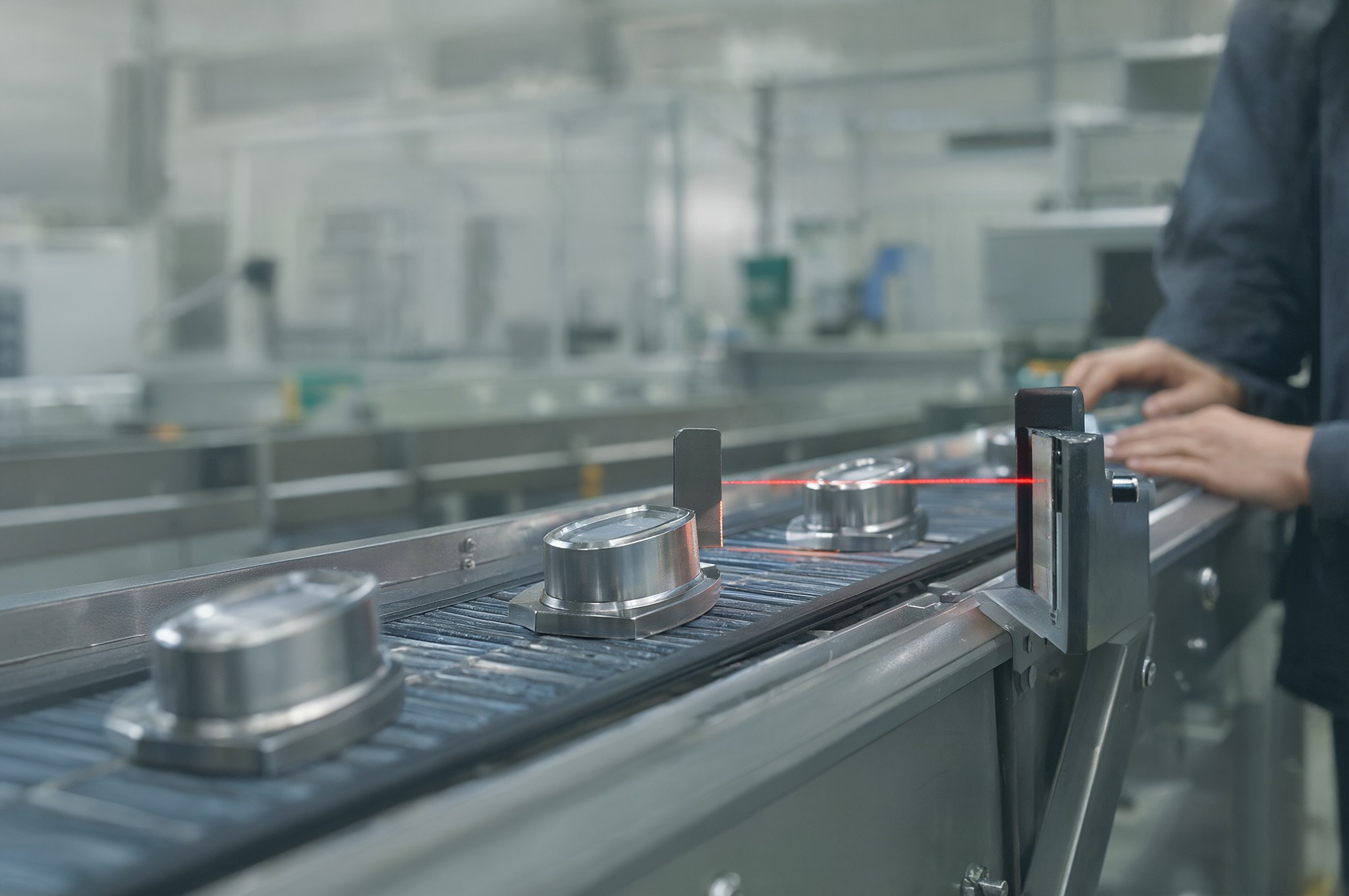
In mechatronics, binary signals are everywhere. On a conveyor belt, a light barrier (German: Lichtschranke) detects whether a workpiece is passing: the light beam is interrupted or not – one bit. The light barrier is connected to a digital input of a programmable logic controller (PLC, German: speicherprogrammierbare Steuerung, SPS), which reads it as 0 or 1. Together with the other inputs – further light barriers, limit switches, push-buttons – it forms the bytes and words with which the controller works.
Image by Qwen-Image 2.1
6.4 The octal system
The octal number system (German: Oktalsystem) has the base 8 and the digits 0 to 7; its name comes from the Latin octo, ‘eight’. After 7 comes 10, after 77 comes 100. LaMeres points out that octal is rarely used [5, p. 7]. It is worth knowing anyway, for two reasons. First, it shows that the rules of positional number systems apply to any base. Second, three bits correspond exactly to one octal digit, from 0002=08 to 1112=78. Octal is therefore a compact way of writing groups of three bits: the octal number 178, for example, stands for 0011112. Converting between octal and binary is correspondingly easy, as you will see in chapter 7.
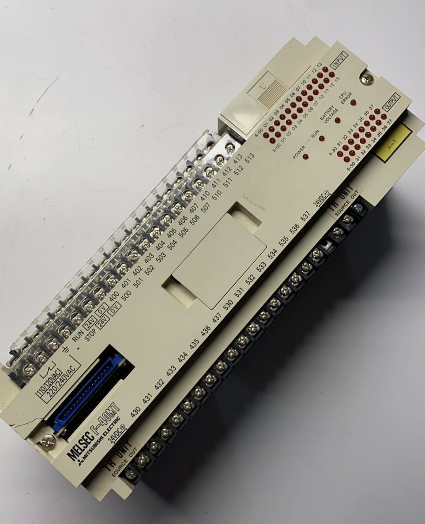
In mechatronics, you meet octal numbers in programmable logic controllers. The compact controllers of the MELSEC-F series by Mitsubishi Electric number their inputs and outputs in octal: the inputs are called X0 to X7, then X10 to X17, the outputs accordingly Y0 to Y7, Y10 to Y17 [7]. Anyone who connects a ninth sensor to such a controller wires it to input X10 – an input X8 does not exist. Each group of eight inputs thus gets its own digit at the second position, and the last digit counts through the eight inputs of the group, from 0 to 7.
The photo shows an older controller of this series, the F-40MT. Its input terminals are labelled 400 to 407 and then 410 to 413: the last digit is octal, so the numbers 408 and 409 do not exist.
6.5 The hexadecimal system
The hexadecimal number system (German: Hexadezimalsystem), ‘hex’ for short, has the base 16. Its name combines the Greek hex, ‘six’, with the Latin decem, ‘ten’: six and ten make sixteen. Since there are only ten Arabic numerals, the letters A to F stand for the values 10 to 15. Four bits – a nibble – correspond exactly to one hexadecimal digit, from 00002=016 to 11112=F16, and two hexadecimal digits describe a byte. This is why hex is the usual way of writing long binary numbers compactly [5, p. 7]. The table shows the values 0 to 15 in all four number systems; it is worth committing it to memory.
Decimal
Binary
Octal
Hexadecimal
0
0000
0
0
1
0001
1
1
2
0010
2
2
3
0011
3
3
4
0100
4
4
5
0101
5
5
6
0110
6
6
7
0111
7
7
8
1000
10
8
9
1001
11
9
10
1010
12
A
11
1011
13
B
12
1100
14
C
13
1101
15
D
14
1110
16
E
15
1111
17
F
In vehicles and machines, control units exchange messages over the CAN bus (Controller Area Network, German: CAN-Bus). In the base format, each message carries an identifier (German: Kennung) of 11 bits, followed by up to eight data bytes [8]. Written in binary, an identifier would be a confusing row of eleven zeros and ones; in hex, it fits into three digits, from 000 to 7FF, and each data byte into two. This is why it makes sense to write CAN messages in hexadecimal. The gateway of our heat pump also reads its values over a CAN bus. In the workshop, a laptop at the on-board diagnostics (OBD) socket of a car reads such messages, as in the photo.
Converting a number into decimal means evaluating the formula of the positional number system from section 6.1 [5]. For a binary number, the base is 2:
N=i=0∑n−1di⋅2i
where:
N is the value of the number in decimal
n is the number of bits
di is the bit at position i, either 0 or 1
For binary numbers, this is particularly easy, because each digit is either 0 or 1: a 0 contributes nothing, and a 1 contributes its weight. So you only add up the weights of the ones.
Example from the smartphone: the battery level is a value from 0 to 100 per cent. A fully charged rechargeable battery shows 100 per cent, written in binary as 11001002, and the conversion confirms it:
Example from the heat pump: its controller could store the hour of the time 23:59 as the binary number 101112:
101112=1⋅24+0⋅23+1⋅22+1⋅21+1⋅20=16+4+2+1=2310
With a little practice, you read small binary numbers at a glance: from the right, the weights are 1, 2, 4, 8, 16, 32 and so on.
7.2 Octal to decimal
For an octal number, the procedure is the same; only the weights are now powers of 8 [5]:
N=i=0∑n−1di⋅8i
where:
N is the value of the number in decimal
n is the number of octal digits
di is the octal digit at position i, from 0 to 7
Example from the Mitsubishi controller in section 6.4: which input is X17? The number after the X is an octal number:
178=1⋅81+7⋅80=8+7=1510
Since counting starts at X0, input X17 is the sixteenth input of the controller. You can also write down the weights of an octal number directly: from the right, they are 1, 8, 64, 512 and so on – each position is worth eight times the one to its right.
A second example shows the largest value of a byte, written in octal:
3778=3⋅82+7⋅81+7⋅80=192+56+7=25510
Octal digits never exceed 7. If a number contains an 8 or a 9, it cannot be octal – just as the controller has no input X8 and no terminal 408.
7.3 Hexadecimal to decimal
For a hexadecimal number, the weights are powers of 16, and the letters stand for their values, from A = 10 to F = 15 [5]:
N=i=0∑n−1di⋅16i
where:
N is the value of the number in decimal
n is the number of hexadecimal digits
di is the hexadecimal digit at position i, from 0 to F, i.e. from 0 to 15
Example from the heat pump: in hex, the number of compressor starts from section 6.2 needs only four digits:
Example from the Controller Area Network (CAN) bus: the largest number that fits into the 11 bits of an identifier is 7FF16:
7FF16=7⋅162+15⋅161+15⋅160=1792+240+15=204710
Together with 0, the 11 bits thus offer 211=2048 codes [8]. The weights grow quickly: the fourth position from the right is already worth 163=4096.
7.4 Decimal to binary
The reverse direction needs a different procedure, the repeated division (German: fortgesetzte Division) by the base of the target system [5]. For binary, the base is 2. Each division gives a quotient and a remainder:
N=q⋅2+r,0≤r<2
where:
N is the number to be divided
q is the quotient, which is divided again in the next step
r is the remainder, the next bit of the result
The first remainder is the least significant bit (LSB) of the result. Divide the quotient again by 2 and note the next remainder, and so on, until the quotient is 0. The last remainder is the most significant bit (MSB). Read from bottom to top, the remainders form the binary number.
Example from the heat pump: its controller keeps the hour, from 0 to 23, and the minute, from 0 to 59, as two separate values. For the time 23:59, the hour 23 is converted like this:
Division
Quotient
Remainder
23 / 2
11
1 (LSB)
11 / 2
5
1
5 / 2
2
1
2 / 2
1
0
1 / 2
0
1 (MSB)
Read from bottom to top, the result is 2310=101112. In the same way, the minute becomes 5910=1110112. You can check both results with the procedure from section 7.1: 16+4+2+1=23 and 32+16+8+2+1=59.
Shortcut for small numbers
Subtract the largest power of two that fits and write a 1 at its position; repeat with the rest until nothing remains. All other positions get a 0. For 59, this gives 59=32+16+8+2+1, i.e. 1110112.
7.5 Decimal to octal
For octal as the target, you divide by 8 [5]. Apart from that, the procedure is the same as in section 7.4: the first remainder is the least significant digit, the last remainder the most significant one. Since a remainder of a division by 8 can only take the values 0 to 7, every remainder is a valid octal digit:
N=q⋅8+r,0≤r<8
where:
N is the number to be divided
q is the quotient, which is divided again in the next step
r is the remainder, the next octal digit of the result, from 0 to 7
Example from the Mitsubishi controller: a sensor is to be wired to the sixteenth input. Counting starts at 0, so the number of this input is 15 in decimal – but what does the controller call it?
Division
Quotient
Remainder
15 / 8
1
7
1 / 8
0
1
Read from bottom to top, 1510=178: the sixteenth input is X17, the reverse of the conversion in section 7.2. A second example with three digits: for 100, the divisions give 100/8=12 remainder 4; 12/8=1 remainder 4; and 1/8=0 remainder 1. Read from bottom to top, 10010=1448. Check: 1⋅64+4⋅8+4=100.
7.6 Decimal to hexadecimal
For hexadecimal as the target, you divide by 16 [5]. The procedure is the same as in sections 7.4 and 7.5, with one addition: a remainder of a division by 16 can take the values 0 to 15, but each one has to fit into a single position. That is why remainders from 10 to 15 are written as the letters A to F; without them, the remainder 15 would look like the two digits 1 and 5:
N=q⋅16+r,0≤r<16
where:
N is the number to be divided
q is the quotient, which is divided again in the next step
r is the remainder, the next hexadecimal digit of the result, from 0 to F
Example from the heat pump: the 8 003 compressor starts, converted back into hexadecimal:
Division
Quotient
Remainder
8 003 / 16
500
3
500 / 16
31
4
31 / 16
1
15 = F
1 / 16
0
1
Read from bottom to top, 800310=1F4316 – the result of section 7.3 in reverse. The largest value of a byte, 255, gives 255/16=15 remainder 15 and 15/16=0 remainder 15, i.e. 25510=FF16. Two hexadecimal digits are thus enough for every byte, which is why colour values and memory contents are written in hex.
7.7 Converting between binary, octal and hexadecimal
Between binary, octal and hexadecimal, there is a shortcut that needs no arithmetic at all [5]. Since one octal digit stands for exactly three bits and one hexadecimal digit for exactly four, you group the bits from the right into groups of three or four – adding leading zeros if necessary – and replace each group by its digit. In the opposite direction, each digit becomes its group of three or four bits. Between octal and hexadecimal, you go via binary: first replace each digit by its bits, then regroup them.
Example from the smartphone display: websites describe a colour with three bytes, one each for red, green and blue, and write them as six hexadecimal digits. On this website, links in light mode appear in a petrol blue with the colour value 284B63:
Colour
Red
Green
Blue
Hexadecimal
28
4B
63
Binary
0010 1000
0100 1011
0110 0011
Decimal
40
75
99
Example from the heat pump: on its control board, a block of four dual in-line package (DIP) switches is labelled with the weights 1, 2, 4 and 8. Together, the four switches form a nibble, and their setting can be written as a single hexadecimal digit. If the switches with the weights 8 and 1 are set to ON, they encode 10012=916; if all four are ON, they encode 11112=F16.
8 Why 1 + 1 = 10 is not a mistake – Binary arithmetic
8.1 Addition with carries
Binary addition works exactly like the written addition you learned at school – only with two digits instead of ten [5]. The numbers are written one below the other, aligned to the right, and added position by position, starting with the least significant bit. For a single position, there are only four cases:
A
B
Sum
Carry
0
0
0
0
0
1
1
0
1
0
1
0
1
1
0
1
The last line answers one of our guiding questions: in binary, 1+1=102, i.e. two. The result needs a second position, exactly as 9+1 becomes 10 in decimal. The 1 that moves into the next position is the carry (German: Übertrag). Programmers have their own joke about it: ‘There are 10 kinds of people: those who understand binary and those who don’t.’
With several positions, the carry is added in the next position. Example: 91+54=145 with 8 bits.
+carry=0011101001101111101001101100101
In a circuit, the number of bits is fixed. If the most significant position also produces a carry, the result no longer fits; LaMeres calls this a carry out (German: Übertrag aus der höchsten Stelle) [5, p. 22]. Example: 111111112+12=1000000002 needs nine bits.
An adder on the kitchen table
In 1937, Stibitz built an adder for binary numbers from relays at home, later called the ‘Model K’ after his kitchen table. It was one of the first steps towards the digital computer.
8.2 Subtraction with borrows
Binary subtraction, too, follows the written subtraction from school [5]. The subtrahend (German: Subtrahend) is subtracted from the minuend (German: Minuend), and the result is the difference (German: Differenz). If, in a position, the digit of the minuend is smaller than that of the subtrahend, the position borrows a 1 from the next higher position; this is the borrow (German: Entleihung). In binary, the borrowed 1 is worth two in the current position, so that 102−12=12.
Example: 13−6=7 with 4 bits.
−borrow=101011110101101
The row ‘borrow’ marks each position that lends a 1 to the position on its right. From the right: 1−0=1. In the second position, 0−1 is not possible, so the position borrows from the third: 102−12=1. The third position now holds only 0 and again has to borrow, from the fourth: 102−12=1. In the fourth position, 0−0=0 remains. Result: 01112=7.
What happens if the subtrahend is larger than the minuend, as in 6−13? Then the most significant position also needs a borrow, but there is no higher position to lend it. The result, −7, cannot be represented with the numbers we have used so far. A heat pump, however, has to deal with exactly such values – for example with an outside temperature of −7 °C. You will see in the next chapter how negative numbers are represented.
9 Below zero – Unsigned and signed numbers
9.1 Unsigned numbers
So far, all our numbers have been positive. In a circuit, however, there is no minus sign – only 0 and 1 – and the number of bits is fixed. A binary number that represents only values from 0 upwards is an unsigned number (German: vorzeichenlose Zahl) [5]. With n bits, there are 2n different codes. Since one of them stands for 0, the range (German: Wertebereich) of an unsigned number is:
0≤N≤2n−1
where:
N is the value of the unsigned number
n is the number of bits
Why does the range end at 2n−1 and not at 2n? Because counting starts at 0: with 3 bits, the eight codes 000 to 111 stand for the values 0 to 7. With 8 bits, the range is 0 to 255. If a counter has reached its largest value, the next count makes it overflow, and it starts again at 0 – like the mileage counter of an old car. Conversely, the formula tells us how many bits a value needs: just enough for its largest value to fit.
Value
Range
Bits needed
Hour of the heat pump’s clock
0 to 23
5, since 25=32
Minute
0 to 59
6, since 26=64
Battery level of the smartphone in per cent
0 to 100
7, since 27=128
Compressor starts of the heat pump so far
0 to 8 003
13, since 213=8192
A counter for the compressor starts must, of course, keep on counting. With 13 bits, it would be full after another 188 starts; with 16 bits, it counts up to 65 535.
9.2 Signed magnitude and one’s complement
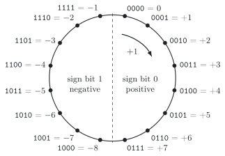
To represent negative numbers – such as the outside temperature of −7 °C – we sacrifice one bit: the most significant bit becomes the sign bit (German: Vorzeichenbit), with 0 for positive and 1 for negative numbers [5]. Numbers with a sign bit are signed numbers (German: vorzeichenbehaftete Zahlen). Their number of bits is always fixed, so that the sign bit always sits in the same position. There are several ways of representing the negative values.
The simplest is signed magnitude (German: Vorzeichen-Betrag-Darstellung): the remaining bits contain the magnitude of the number. With 4 bits, 01112 is +7 and 11112 is −7. In one’s complement (German: Einerkomplement), a negative number is formed by inverting all bits of its positive counterpart: +7 is 01112, and −7 is 10002.
Both representations share a weakness: there are two codes for 0, a ‘plus zero’ and a ‘minus zero’. This wastes a code and makes arithmetic circuits more complex. Signed magnitude has a second problem: an ordinary adder calculates (−5)+1=−6 instead of −4, because it adds the magnitudes. One’s complement solves this problem but keeps the double zero [5, pp. 26–29]. The table compares the 4-bit codes; its last column shows the representation that avoids both weaknesses.
Code
Signed magnitude
One’s complement
Two’s complement
0000
+0
+0
0
0001
+1
+1
+1
0010
+2
+2
+2
0011
+3
+3
+3
0100
+4
+4
+4
0101
+5
+5
+5
0110
+6
+6
+6
0111
+7
+7
+7
1000
−0
−7
−8
1001
−1
−6
−7
1010
−2
−5
−6
1011
−3
−4
−5
1100
−4
−3
−4
1101
−5
−2
−3
1110
−6
−1
−2
1111
−7
−0
−1
9.3 Two’s complement
The representation that modern computers use is the two’s complement (German: Zweierkomplement) [5, p. 26]. The code of a negative number is obtained by subtracting its magnitude from 2n:
C=2n−∣N∣
where:
C is the code of the negative number N, read as an unsigned binary number
n is the number of bits
∣N∣ is the magnitude of the negative number N
In practice, there is a quicker way that gives the same result: invert all bits of the positive number and add 1. Taking the two’s complement of a negative number gives its positive counterpart again. The only exception is the smallest number: with 4 bits, −8 is 10002, and inverting and adding 1 gives 10002 again, because +8 does not fit into 4 bits. Example from the heat pump: below the bivalence temperature (German: Bivalenztemperatur) of −7 °C, the heat pump gets support from a second heat source. With 8 bits, the controller could store this temperature like this:
Step
Bits
Positive number +7
0000 0111
Invert all bits
1111 1000
Add 1: −7
1111 1001
The formula confirms the result: 28−7=249=111110012=F916. In the same way, the lower operating limit (German: untere Einsatzgrenze) of −20 °C becomes 111011002=EC16; below it, the heat pump can no longer operate, and only the emergency heating (German: Notheizung) heats – an electric heating rod (German: Heizstab) of up to 8.8 kW that the controller of the heat pump switches on in stages and that heats the water flowing through it.
There is no double zero any more: all 2n codes are used, and the range is:
−2n−1≤N≤2n−1−1
where:
N is the value of the signed number
n is the number of bits
With 8 bits, the range is −128 to +127. The sign bit still shows at a glance whether a number is negative.
10 From the real world into bits and back – Introduction to A/D and D/A conversion
10.1 From sensor to actuator
This chapter only takes a brief look at the topic: with a very common technical principle, it shows how analogue and digital quantities are related, and it gives a first application of binary numbers. We will deal with analogue-to-digital and digital-to-analogue conversion in detail in DET-11.
As we saw in chapter 5, analogue technology remains at the border between the physical world and the digital world. A temperature, a sound or a battery voltage is analogue, while the controller that processes it is digital. Two converters build the bridge [9]: an analogue-to-digital converter, or A/D converter (German: A/D-Wandler) for short, turns an analogue voltage into a number, and a digital-to-analogue converter, or D/A converter (German: D/A-Wandler) for short, turns a number back into a voltage. Their tasks are the A/D conversion (German: A/D-Wandlung) and the D/A conversion (German: D/A-Wandlung).
A sensor first turns a physical quantity into a voltage, and the A/D converter turns this voltage into a number. A microcontroller processes the number, and a D/A converter turns the result back into a voltage, which finally drives an actuator.
In the smartphone, a microphone turns your voice into a voltage, an A/D converter turns it into numbers, and the processor compresses and transmits them. On the phone of the person you are calling, a D/A converter turns the numbers back into a voltage, which drives the loudspeaker.
In the heat pump, the controller digitizes the signals of its temperature sensors. On this basis, it switches pumps and valves via relays.
11 What have you learnt? – Summary and answers to the guiding questions
11.1 The building blocks of knowledge
Structure and organization of the courses: Twelve sessions, each with a lecture and exercises. This script contains the complete content; the textbook by LaMeres and the logic simulator complement it.
Form of assessment: An ILIAS eAssessment of 60 minutes in the computer room on the Gütersloh campus, with a non-programmable calculator as aid. The mock exam in DET-12 prepares you for it.
Terms and definitions: Analogue signals map information continuously, digital signals encode it with discrete values. The bit is the smallest unit of information; in positive logic, LOW stands for 0 and HIGH for 1; transistor–transistor logic works with a supply voltage of 5 V.
Number systems: In a positional number system, each digit is weighted with a power of the base: 10 in decimal, 2 in binary, 8 in octal and 16 in hexadecimal.
Base conversion: Into decimal by adding up the weighted digits, from decimal by repeated division, and between binary, octal and hexadecimal by grouping three or four bits.
Binary arithmetic: Addition with carries and subtraction with borrows, exactly as in decimal; with a fixed number of bits, a carry out can occur.
Signed numbers: The most significant bit is the sign bit. One’s complement – invert all bits – keeps two codes for 0. Two’s complement – invert and add 1 – uses all codes and covers the range from −2n−1 to 2n−1−1.
Application – from sensor to actuator: Analogue-to-digital (A/D) and digital-to-analogue (D/A) converters link the analogue and the digital world; the details follow in DET-11.
11.2 Answers to the guiding questions
What awaits you in this module, and how will you show at the end what you can do?
Twelve sessions lead you from the single bit via logic operations, circuits and counters to programmable devices, with the smartphone and the heat pump as examples. Each session combines a lecture with exercises, supported by this script, the textbook and the logic simulator. At the end, you show what you can do in a 60-minute eAssessment in ILIAS; the mock exam in DET-12 lets you rehearse it.
Why is 1 + 1 = 10 not a mistake?
Because in the binary system there are only the digits 0 and 1. The sum two no longer fits into one position, so a carry moves to the next position – just as 9+1=10 in decimal. Read in binary, 102 means two, and 1+1=102 is correct.
How can a heat pump that knows only two states, on and off, show the time 23:59, count 8 003 compressor starts and store an outside temperature of −7 °C?
It stores every value as a binary number with enough bits. The hour 23 is 101112 and needs 5 bits, the minute 59 is 1110112 and needs 6 bits. The 8 003 compressor starts are 11111010000112=1F4316 and need 13 bits; a 16-bit counter has room for many more. The temperature −7 °C can be stored in two’s complement, with 8 bits, for example, as 111110012. For us, the controller converts all these numbers back into decimal.
Where do I look things up? – Sources and references
All sources that I cite in this script with a number in square brackets, such as [5], are listed on the page References. There you will also find the books that I recommend for looking things up, the image licences and a note on the use of AI.