
Prof. Dr. Thorsten Jungmann (last updated 2025-10-15)
Overview of this lesson
What is this lesson about? – The guiding questions:
- What does ‘studying’ mean?
- What is the Electrical Engineering module about in terms of content?
- What prior knowledge is assumed?
- How are the courses designed and how do they run?
- What does the examination look like?
- What can you do to complete the module successfully?
What will you be able to do at the end of this lesson? – The intended learning outcomes:
- You can identify the resources required for this module (time, places of learning, learning tools, motivation) and plan how you will use them effectively.
- You understand what knowledge and competences are assumed, recognize any gaps and can plan how to make up for them.
- Ideally, you can embark on our shared journey through the fundamentals of electrical engineering and let go of any reservations you may have.
What will you know at the end of this lesson? – The building blocks of knowledge:
- The structure and objectives of the courses, lessons, exercises and guided self-study, how they interact to achieve the module objectives and how they fit into your degree programme.
- Fundamentals of electrical engineering that you should already know from school.
- The didactic concept and the methods and tools used by the lecturer.
- The form and procedure of the examination in which you will demonstrate that you have achieved the module objectives.
- The resources I expect you to use for this module.
- Me as your lecturer and my expectations of our collaboration in this module.
How is the content organized? – The structure:
- 1 Studying successfully – Nothing comes from nothing!
- 2 What does the course build on? – Necessary prior knowledge from school
- 3 How do I teach? – Didactic principles of my courses
- 4 The examination – your stage
- 5 What is this module about? – Introduction to the content
- 6 Caution! – Safety rules for handling electricity
1 Studying successfully – Nothing comes from nothing!
What does ‘studying’ mean?
Studere (Lat.): to strive for something, to pursue something, to aspire to something, to devote oneself intensively to a matter on one’s own initiative, to engage in something scientifically, to learn.
Where does success come from? From your behaviour during your studies!
- Actively participate in the classes, and while doing so …
- listen attentively,
- take notes,
- ask questions,
- take an interest (or let yourself be interested),
- discuss,
- join in the exercises.
- Prepare for and follow up on the classes.
- Practise applying the tools, models and methods you have learned.
- Learn, work and sometimes celebrate together as a group.
- Draw on solid prior knowledge and refresh it if necessary.
- Keep the goals in sight from the very beginning.
NOW:
Set up a notebook and take notes, e.g. in the Cornell note-taking format.
Cornell dotted paper HSBI.pdf
FOLLOW-UP of today's lesson:
Question your prior knowledge and refresh it if necessary.
2 What does the course build on? – Necessary prior knowledge from school
I assume the knowledge, abilities and skills that, according to current educational standards, are associated with the (subject-specific) university entrance qualification and the successful completion of the STEM subjects at school.
Simple electric circuit from physics lessons
Technical vocational training adds important practical experience to this prior knowledge. If in doubt, however, it does not replace the school education of secondary levels I and II.
To understand the fundamentals of electrical engineering, you need the content of the following subjects:
Important!
Feel free to check on the individual detail pages what exactly is expected.
I cannot and do not want to make up for the gaps from school that some of you bring with you, while others would (rightly) watch on, bored.
Therefore: if you know of or notice any gaps here, it is essential that you acquire the missing competences very soon to avoid problems!
3 How do I teach? – Didactic principles of my courses
Studying at university differs in some respects from lessons at school. The principle is not: ‘Only what has been taught is relevant in the examination.’ Instead: what you must be able to do in the examination is set out in the module handbook. It goes without saying for me that I adhere to what is in the module handbook and that the stated objectives and content shape my courses.
My courses work like this:
- I show and explain once how it works. (lecture/seminar-style class)
- e.g. a formula
- I demonstrate it with an example. (lecture/seminar-style class)
- there is a worked example for every formula
- I answer questions about the procedure so that nothing remains unclear.
Exceptions:- If the question relates to prior knowledge expected from school, I refer you to it and perhaps explain it briefly if there is time. Or perhaps not.
- If the question relates to something I explained earlier but you were not present or were not listening, I refer you to the script and to your fellow students, whom you can ask.
- If the question relates to material from another course, I refer you to that course and perhaps answer the question briefly if I know/can. Perhaps I will just refer you to the other course.
- I give you exercises to practise what has been explained, support you in doing so and answer your questions – for exceptions, see above. (individual/seminar-style class)
- I give you suggested solutions or model solutions so that you can compare them with your own solutions. I am happy to answer questions about them – for exceptions, see above. (individual/seminar-style class)
- For further practice, I give you tips on where to get additional exercises. (individual/guided self-study)
This may sound harsh at first, but in my view it reflects the principle of studying at university.
3.1 Learning as an active process under your own responsibility
At university, you yourself are responsible for your learning success!
You act. You get what you need.
An old piece of wisdom among teachers:
Students learn from what they do. Ralph Tyler describes learning as taking place through the active behaviour of the student.
‘It is what he does that he learns, not what the teacher does.’ (Tyler, R. W., 1949: Basic Principles of Curriculum and Instruction. The University of Chicago Press. Chicago & London. p. 63)
Like at a buffet
Instead of ‘all you can eat’, the offer comprises ‘more than you can eat’.

Photo: user:takoradee, CC BY-SA 3.0, via Wikimedia Commons

The analogy to my courses:
- I cook tasty dishes with good ingredients.
- I arrange them as appealingly as possible and present them transparently so that everyone knows what they are.
- For unfamiliar dishes, I show how to handle and eat them.
- After that, it is up to the guests to help themselves and eat – and, if necessary, to ask when something is missing or unclear.
- It is the guests’ responsibility …
- … to put the dishes on their plates in the right amount and the right combination – individually, depending on their eating habits and goals.
- … to eat at the right pace.
- … to pay attention to feeling full and to take in enough food for the time until the next meal.
Not only at the buffet but also in class, it is good to discover something familiar so that you are not completely lost. That is why I use everyday objects as recurring examples to help you get started with each new topic.
3.2 Everyday objects as recurring examples
I will keep coming back to the following everyday objects to pick you up where you are, so that we can examine the various details of the devices or systems and go into them in more depth.
LED torch with solar cell and dynamo
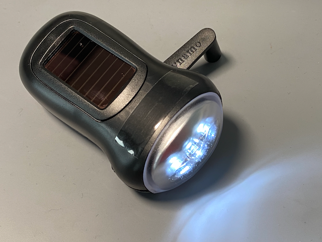
The obvious:
- Crank for charging (‘dynamo’)
- Solar cell for charging
- 3 light emitting diodes as light sources in the reflector
- On/off switch
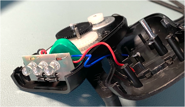
The hidden:
- Generator and solar cell as sources
- Electric network of sources, rechargeable battery, diodes, light emitting diodes, resistors, LEDs, electric lines and a circuit board
🔗 Detail page on the LED torch
Extension lead – multiple socket-outlet with supply cable
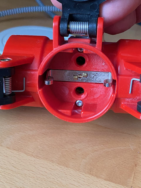
The obvious:
- A supply cable
- Three protective-contact socket-outlets, three-pole: L/N/PE (PE = protective conductor, metal clip, running horizontally in the image)
- Spring-loaded protective shutters on all three socket-outlets
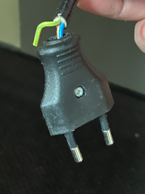
The hidden:
- faulty here: supply cable only two-pole (without PE, i.e. without protection against a fault to the enclosure in metal appliances such as the kettle)
- correct would be: three-core supply cable for three-pole socket-outlets with the correct cross-section
🔗 Detail page on the multiple socket-outlet with supply cable
Case fan
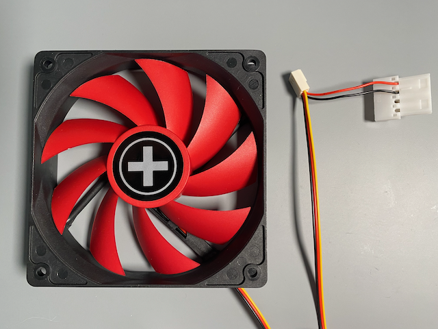
The obvious:
- Brushless DC motor
- Three-core connecting cable (BK/RD/YE)
- Rated rotational frequency
- Rated voltage DC
- Rated current
The hidden:
- Stator with windings → inductors → inductance
- Rotor with magnet
- Magnetic sensor for measuring the rotational frequency (‘tacho signal’)
- Rotational frequency controllable via the voltage
3.3 Industrial examples
Control board of a heat pump
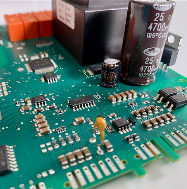
The obvious:
- Transformer
- Capacitors
- Relays
- Integrated circuits (ICs)
- Resistors
- Voltage regulators
- Diodes
- Connection terminals
- Circuit board with traces
The hidden:
- It controlled an air-to-water heat pump.
🔗 Detail page on the control board
A device/system from your professional environment
In the current Mechatronics degree programme, as part of the practical assignment, you technically characterized one of the three largest consumers in your company in a profile. This device or system will serve as an example again and again throughout the course.
3.4 Water analogy as a thought model
When introducing the electric field, I already mentioned the river as an example. The fact that everyone has experience of the force of water can be put to good use to explain certain phenomena and effects of electrical engineering by analogy with water.
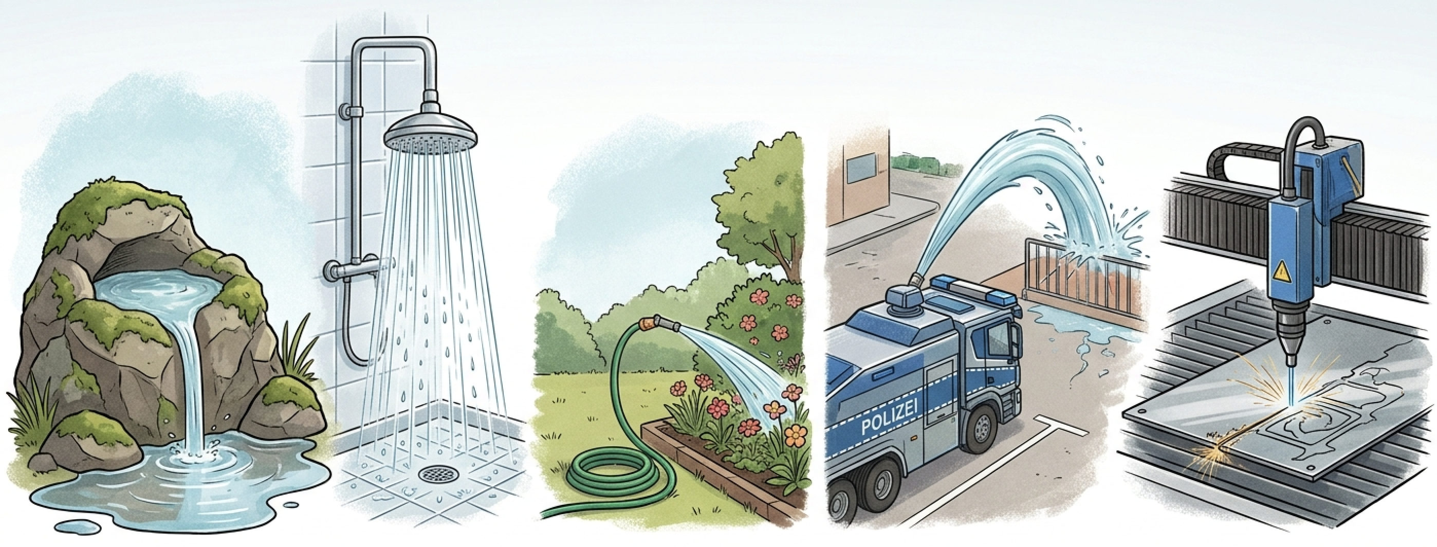
Examples of the force of water
What do you notice about the order of the words in the image?
The examples show (from top to bottom) that the pressure and volume flow rate of water can have different effects: the spring babbles along, the shower pleasantly rinses the skin, the jet from the garden hose moves leaves and loose dirt, the high-pressure cleaner removes firmly adhering dirt, the water cannon moves people (and crowds), and in water jet cutting the water even separates fragments out of solids.
The water model lets you understand many properties of voltage and current. Flowing water consists of molecules that move under pressure. It has a lot in common with flowing current, which consists of electrons that move under electric voltage. Depending on the pressure, more molecules flow through the same pipe.
- The water pressure corresponds to the electric voltage.
- The volume flow rate corresponds to the electric current.
- The garden hose corresponds to the electric line.
- The valve corresponds to the switch or the resistor.
3.5 Animated simulation model
An animated simulation model offers insights and things that we cannot make tangible even with the water analogy. It makes the invisible visible, here: the rectification of an alternating voltage into a direct voltage with a smoothing capacitor.
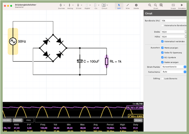
Rectifier (German: Gleichrichter)
The image shows an electric circuit that converts an alternating voltage (e.g. from the mains or produced by a generator) into a direct voltage.
From left to right:
- AC source (input voltage)
- 4 diodes in a bridge network (diode rectifier)
- Capacitor for stabilizing the output voltage
- Load resistor (representing an electric circuit that is supplied with the direct voltage, e.g. a control board or a rechargeable battery to be charged)
In the lower area, the simulation makes the waveforms of the input voltage (yellow) and the output voltage (violet) visible.
For this, I use the software iCircuit.
3.6 Textbook
In addition to this script, you can follow everything in this textbook. Other textbooks will of course do as well, but this one matches my course in terms of its ‘altitude’.
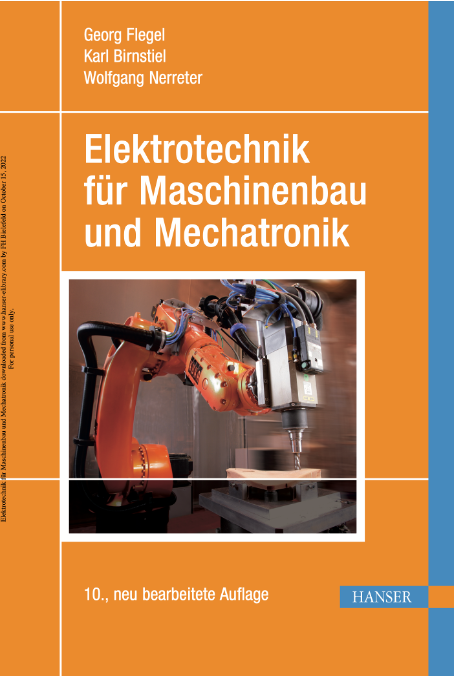
ELEKTROTECHNIK FÜR MASCHINENBAU UND MECHATRONIK
10th, revised edition
- Georg Flegel,
- Karl Birnstiel and
- Wolfgang Nerreter
352 pages
eISBN 978-3-446-44773-8
Print ISBN 978-3-446-44496-6
© 2016 Carl Hanser Verlag GmbH & Co. KG
Link to the book for my students
How do I get books for my studies?
Library
- borrow
- scan from the course reserve
- obtain via interlibrary loan
- suggest a purchase
Bookshop- buy
4 The examination – your stage
At the end of the semester, I prepare a stage for you on which you can show your abilities. Stage fright is okay, but exam anxiety should not arise – it is all a matter of practice! Really!!

eAssessment (online exam)

- Knowledge, comprehension and calculation tasks
- Participation
- on a computer (not a tablet or smartphone)
- in the university’s computer room
- Permitted aids
- 2-sided, handwritten formula collection on paper
- with name and matriculation number, to be handed in after the examination
- your own non-programmable calculator without graphing function (Casio FX-82…)
- 2-sided, handwritten formula collection on paper
- Mock examination
- get to know the question types
- test the technology
- evaluate your learning progress
- Support on the day of the examination
- instructions for taking the examination
- access password
- technical questions
Now:
Start creating your own handwritten formula collection now!
You will need it for the examination, because no aids other than the formula collection and a simple calculator are permitted. – Simply label a blank page in your notebook ‘Formula collection EE1’. Done!
By the next class:
Get yourself a Casio FX-82 (recommended: MS-2; other FX82 models are also permitted) so that you can practise using it. You will need it for the examination, because no aids other than this calculator and your own handwritten formula collection are permitted.
5 What is this module about? – Introduction to the content
Electrical engineering is ...
… an engineering science that deals with research and development as well as the production, assembly and maintenance of electrical devices and electrical installations that are based, at least in part, on electrical energy.’ (German Wikipedia: Electrical engineering, accessed 5 October 2024)
5.1 Fields of application of electrical engineering
Electrical engineering forms a broad foundation for various fields of application in which engineers can work. This interdisciplinary orientation makes it possible to integrate mechanical, electrical and computing components into complex systems.
5.1.1 Power engineering
Power engineering deals with the generation, transmission, distribution and use of electrical energy. The activities of engineers include:
- Development and design of energy systems
Planning and construction of installations in power stations, municipal utilities and grids - Renewable energies
Integration of solar power plants, wind turbines and battery storage systems - Power electronics (German: Leistungselektronik)
Design of switching circuits for electromobility, industry and aviation
Typical orders of magnitude
- Power: –
- Voltage: –
- Current: –
5.1.2 Automation engineering
Automation engineering covers the measurement, open-loop control and closed-loop control of automatically operated installations. Areas of application are:
- Development of automation systems
Design, programming and commissioning of programmable logic controller, robotics and CNC systems - Industrial applications
Computer-aided production machines, traffic control systems, building management systems - Measurement and control engineering
Sensor technology, data processing in control units, actuator control
Typical orders of magnitude
- Power: –
- Voltage: –
- Current: –
5.1.3 Medical engineering
Medical engineering links the fundamentals of electrical engineering with medical applications. Here, engineers work mainly in these areas:
- Development of medical devices
Ultrasound, MRI, X-ray, defibrillators, pumps - Biomedical systems
Pacemakers, implants, protective mechanisms for tissue - Wearable medical technology
Wearables, mobile diagnostic and monitoring systems
Typical orders of magnitude
- Power: –
- Voltage: –
- Current: –
5.1.4 Communications engineering
Communications engineering combines electrical engineering, computer science and physics to transmit information. Activities for engineers include:
- Communication systems
Mobile communications, internet networks, satellite and broadcasting technology - Signal processing
Modulation, demodulation, filter and codec development - Microsystems engineering
Chip and sensor technology for smartphones and IoT devices
Typical orders of magnitude
- Power: – (transmission power)
- Voltage: –
- Current: –
5.1.5 Automotive engineering
Automotive engineering is currently shaped by electrification and driver assistance systems. This includes:
- Electromobility
Electric drives, battery management, charging infrastructure - Driver assistance systems
ABS, ESP, parking assistance, road and lane-keeping assistants - Automotive electronics
Control units, sensor fusion, CAN bus networking
Typical orders of magnitude
- Power: –
- Voltage: – (high-voltage on-board power supply)
- Current: –
5.1.6 Robotics
Robotics combines mechanical engineering, electrical engineering and computer science. Activities for engineers:
- Industrial robots
Programming, motion control, gripping systems - Service robots
Assistance in the household, healthcare, retail - Sensors and actuators
Perception of the environment, motion control
Typical orders of magnitude
- Power: –
- Voltage: –
- Current: –
5.1.7 Building services engineering
Building services engineering links electrical engineering with automation in construction. This includes:
- Building automation
central control of lighting, air conditioning, access (KNX, BACnet) - Smart home technologies
IoT networking, energy efficiency, comfort solutions - Security technology
Access control, intrusion and fire protection systems
Typical orders of magnitude
- Power: –
- Voltage: –
- Current: –
5.1.8 Aerospace engineering
Highly reliable electronics for aviation and space systems. The activities of engineers include in particular:
- Avionics
Navigation, flight control, on-board power supplies - Electrification of aviation
Electric engines, fuel cell and battery integration - Unmanned aerial vehicles (UAV)
Drone development, autonomy, sensor data fusion
Typical orders of magnitude
- Power: – several
- Voltage: DC, AC (); up to several (space flight)
- Current: – , up to several at peak operation
5.2 In theory: Maxwell’s equations
Besides the practical applications, the purpose of (academic) study is to understand the fundamentals theoretically as well. Theory is the foundation of all applications. Maxwell’s four equations describe the fundamentals of electrical engineering comprehensively in theory.
(1) Electric charges generate electric fields (Gauss’s law of electrostatics)
Wherever positive or negative electric charges are concentrated, the electric field lines run from the location of positive charge (+) to the location of negative charge (-). The electric flux density (or the density of the electric field lines) at a point is proportional to the density of the electric charges at that point.
In other words, electric field lines diverge at positive charges (or accumulations of charge) and converge at negative charges. Mathematically, this means:
Read: ‘Nabla D equals rho el.’
where:
- the divergence operator (tests for divergence/convergence via the scalar product)
- the electric flux density (unit: ), with
- electric field constant (permittivity of vacuum)
- relative permittivity (of the material)
- the space charge density (unit: )
(2) Magnetic fields have no sources. (Gauss’s law for magnetism)
Unlike electric fields, magnetic field lines have neither a point of divergence nor a point of convergence, i.e. neither a beginning nor an end. They form closed loops. This means that there are no magnetic monopoles. Magnets are dipoles. Expressed mathematically:
Read: ‘Nabla B equals zero.’
where:
- the divergence operator
- the magnetic flux density (unit: ) with
- vacuum permeability (permeability of vacuum)
- relative permeability (of the material)
- magnetic field strength
(3) A time-varying magnetic field induces an electric field. (Faraday’s law of induction)
When the magnetic field changes, an electric field is generated in the surrounding space (electromagnetic induction). This is the fundamental principle of electromagnetic induction as used in generators and transformers. Expressed as a formula:
Read: ‘Nabla cross E equals minus partial B with respect to t.’
where:
- the rotation operator (tests for rotation/vortices via the vector product)
- the electric field strength (unit: )
- the partial derivative with respect to time
- the magnetic flux density
(4) Current and a changing electric field generate a magnetic field. (Ampère’s law with Maxwell’s addition)
A magnetic field arises wherever current flows, and also when the electric field changes. This is the basis for how electromagnets and electromagnetic waves work. Mathematically, this can be expressed as follows:
Read: ‘Nabla cross H equals J plus partial D with respect to t.’
where:
- the rotation operator
- the magnetic field strength (unit: )
- the current density (unit: )
- partial derivative with respect to time
- the electric flux density
In theory, there is nothing to add to Maxwell’s four equations. 😉
- Electric charges generate electric fields. These exert forces on mobile charge carriers located in them and set them in motion.
- Moving charge carriers generate magnetic fields.
- Changing electric fields generate magnetic fields.
- Magnetic fields influence the motion of charge carriers.
5.3 In practice: devices and installations
Even if it is not always visible, the scientific theory is contained in the electrical devices and installations that not only shape our everyday life but in many cases make life as we know it possible in the first place.
In practice, the physical phenomena surrounding electric and magnetic fields are used in many ways. Here are some examples:
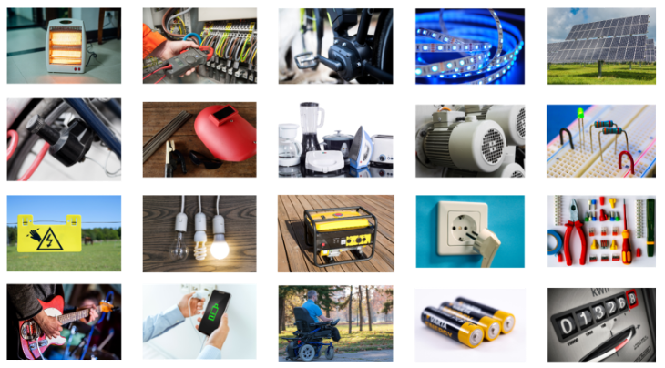
20 practical examples of electrical systems
What do you recognize in this overview, and what connection to electrical engineering do you see in each case?
From top left, row by row, to bottom right:
- Heating device; clamp-on ammeter at a control cabinet; electric motor of an e-bike; LED strip; photovoltaic generator
- Generator (‘dynamo’ on a bicycle); welding machine with face shield; household appliances; electric motor on an industrial scale; breadboard with jumper wires, light emitting diode and resistors
- Electric fence; lamps (incandescent bulb, energy-saving lamp, LED lamp); generator (‘backup power generator’ for private use); protective-contact socket-outlet with plug; power tools
- Electric guitar; smartphone with charger; small electric vehicle; batteries (AA cells); energy meter
5.4 Our leading character: the electron
The leading character of this script is the electron (German: Elektron), the negative elementary charge (German: negative Elementarladung), with its effects – these differ depending on whether it is at rest, moving uniformly or being accelerated.

Effects:
- At rest, the electric charge produces electric fields.
- Its uniform motion generates magnetic fields, which in turn set electric charges in motion.
- If its motion changes, electromagnetic waves (changing fields) arise.
| Profile | |
|---|---|
| Size | An electron is point-like and has no detectable extent. Models assume a radius in the order of . |
| Mass | |
| Electric charge |
The counterpart to the electron is the proton, the positive elementary charge. It is about 1 000 times larger than an electron, weighs about 1 840 times as much and has the electric charge . Even though the proton plays an important role in chemistry and, as the counterpart to the electron, in principle keeps nature in balance, it plays no direct role in the fundamentals of electrical engineering.
In electrical engineering, the absence of one or more electrons means a positive charge (German: positive Ladung), and the presence of one or more surplus electrons means a negative charge (German: negative Ladung).
Example: electric charges in a smartphone's rechargeable battery
An iPhone 16 has a battery capacity of . When fully charged, about 80 sextillion () electrons are waiting to be used. With moderate use, a current of about flows, most of which goes to the display. Per hour, just under 5 sextillion then drift from the negative terminal (-) through the electric circuits to the positive terminal (+) of the rechargeable battery, because the electric field between (+) and (-) makes them move.

Image source: Jacob Elektronik

5.5 Coulomb’s law: force between electric charges
‘Positive and negative charges attract each other.’ You know this sentence.
Coulomb’s law describes the force between two electric point charges more precisely.
5.5.1 Basic form (magnitude of the force)
where:
- the magnitude of the force in (Newton)
- the electric charges in (Coulomb)
- the distance between the electric charges in (metres)
- the electric field constant
Or, in short, with the Coulomb constant :
5.5.2 Vector form
where:
- the unit vector in the direction of the connecting line
- the force that electric charge 1 exerts on electric charge 2
5.5.3 Key statements
Direction of the force:
- Like charges (both + or both −): the force is repulsive
- Opposite charges (+ and −): the force is attractive
Proportionalities:
- (proportional to the product of the electric charges)
- The more electric charge, the stronger the force
- (inversely proportional to the square of the distance)
- The greater the distance, the weaker the force
5.5.4 Example calculation
If you rub a thin plastic bag () on fabric, it becomes electrically charged. It then sticks to a wall or door that is not completely free of dirt and dust. We calculate the role that the Coulomb force plays in this:
Electric charges: and at a distance of :
At , the force is almost twice the weight-force of the bag and is attractive (opposite charges: bag negative, door/wall positive). The bag sticks to the vertical surface against gravity.
Discussion of the example
This example is somewhat idealized. In reality, polarization or electrostatic induction, i.e. the displacement of electric charges in the door/wall, also plays a role between the bag and the door or wall – as does the friction between the surfaces. However, this can be disregarded when, as here, the point is the basic attraction between two electric charges.
5.6 A first model: field lines in the electric field
Unlike the bag sticking to the door, many other phenomena in electrical engineering cannot be observed. They are invisible to the human eye and cannot be detected by our other senses either. Unlike some animals, we have, for example, no sense for magnetic fields, and we only perceive electric fields above a certain magnitude. Our hair, for example, then aligns itself with the field, but this already requires a field so strong that it is not without danger to us.
In cases like these, models are used. A model always represents a section of reality, namely the one that is useful for the intended consideration.
One effect of electric charges is an electric field. It is symbolized or modelled by field lines, as shown below. At positive charges or charge accumulations (locations with a deficit of electrons), the electric field lines diverge; they spread apart there. At negative charge accumulations (locations with a surplus of electrons), they converge; they come together. We can represent this graphically and thus understand it better. The field lines originate at the location of the positive charge and end at the negative charge.
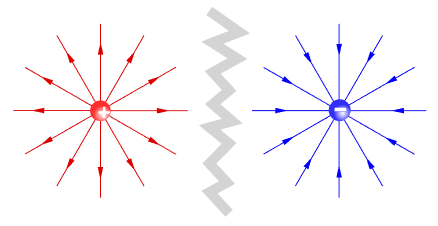
Important convention
In this script, fields are always considered homogeneous. This means that we consider fields at a sufficiently large distance from their origin, so that the field lines there are evenly distributed and run parallel.
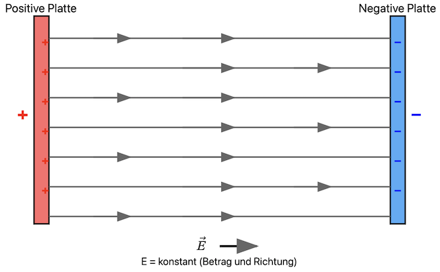
Homogeneous electric field
The electric field can be understood as a force field. In this field, an electron experiences a force towards the origin of the field, i.e. towards the positive pole. This is like a wind tunnel or a river in which a body is moved in one direction by the flow.
How strongly the field acts on the electric charges is expressed by the electric field strength .
The electric field strength in describes how strong the electric field is at a particular point and thus characterizes the spatial distribution of the force that an electric field exerts on an electric charge. The greater the electric field strength, the greater the force on the electric charge .
Here, is a single electric charge.
Details on the electrical quantities
For all electrical quantities that appear in this script – such as the electric charge and the electric field strength – there are detail pages with all the important information on the respective quantity. The pages are linked in the lessons and also here in this info text. On the separate detail pages, you can read up on everything you want or need to know at the right time, without interrupting the ‘flow’ of reading the lesson. At this point, I recommend taking a look at the two detail pages.
5.7 Phenomena, methods, models and tools
So far, you have become acquainted with three electrical phenomena: electric charges, the forces they exert on each other and the resulting electric field. You have also seen field lines as a model of the electric field.
In this course, further phenomena, methods, models and tools will follow. Once you have successfully worked through the lessons, you will be familiar with these topics:
- Electric charges at rest and in motion; electric fields
- Electrical quantities and units
- Symbols, schematics, formulas, graphs, tables
- Passive components, their properties and functions
- Sources (DC/AC, current/voltage, ideal/real, equivalent)
- Resistance, Ohm’s law, temperature dependence
- Capacitance, capacitor, static and dynamic behaviour
- Inductance, inductor, static and dynamic behaviour
- Models and methods for network analysis and calculation (equivalent resistance, series/parallel connection, voltage/current divider, bridge network, Kirchhoff’s laws, Helmholtz’s superposition theorem, maximum power transfer)
5.8 Intended learning outcomes
What can you then do with your knowledge of the phenomena, methods, models and tools?
- You identify, describe and explain the elementary relationships and laws of electrical engineering in technical systems.
- In doing so, you use the associated technical terms confidently.
- You analyse, describe and calculate simple direct current networks and certain alternating current networks.
- Through insight into current fields of application, you can classify and assess the technical and economic significance of electrical engineering.
5.9 Cross-cutting competences
Much of what you will learn in this course is useful not only for electrical engineering. So-called cross-cutting competences also develop, which will help you to sit firmly in the saddle throughout your studies and afterwards in your career.
These cross-cutting topics are not always covered explicitly but occur implicitly in the courses:
- Technical vocabulary that helps you, as an engineer, to take part competently in project meetings and technical discussions
- Mathematics as the ‘language’ in which engineers communicate with each other and with members of other disciplines about systems, their nature and their functions
- Tables, equations and graphs in which the relationships between physical or electrical quantities are illustrated qualitatively and/or represented quantitatively (as an alternative to equations)
- Methods for modelling systems or subsystems, calculating quantities in electric circuits, dimensioning components and implementing functions
- Customs of electrical engineering, so that you do not ‘look green’ when dealing with ‘old hands’ and practitioners
6 Caution! – Safety rules for handling electricity
Better safe than sorry!
One of the most important customs around electrical installations, and at the same time an important safety rule, is: if you don’t know what you are doing, keep your hands in your pockets and don’t touch anything.
When you handle electricity, the five safety rules according to VDE always apply, and in the laboratory there are also supplementary laboratory safety rules:
6.1 Five safety rules (VDE 0105-100)
- Disconnect from mains – switch off all poles.
- Secure against reconnection – e.g. lock it or attach a warning sign.
- Verify that the installation is dead – use a two-pole voltage detector and test it before and after.
- Carry out earthing and short-circuiting – absolutely necessary for medium and high voltage.
- Provide protection from adjacent live parts – e.g. insulating mats, protective covers.
6.2 Supplementary laboratory safety rules
- Wear personal protective equipment (PPE) – insulating gloves, safety goggles, flame-retardant clothing, safety shoes.
- Use only tested, suitable tools – insulated tools according to VDE, do not use damaged cables or plugs.
- Take measurements on live parts only when necessary – CAT-rated measuring instrument, safe test leads, no exposed probe tips in the working area.
- Keep safety distances – minimum distances according to VDE, depending on the rated voltage.
- Operate devices only in technically perfect condition – report defective devices immediately, do not repair them yourself without approval.
- Work only under the supervision of a qualified electrician – students must not work alone on live installations.
- Keep your workplace tidy and clean – arrange electric circuits clearly, do not run loose cables across the floor, no food or drinks in the laboratory.
- Know what to do in an emergency – know the location of the emergency stop, main switch, fire extinguisher and first aid kit.
- Report accidents and near misses immediately – even in the case of supposedly insignificant electric shocks.
Where do I look things up? – Sources and references
When I want to look something up, I use these books, and I recommend them to you too:
BOOKS
- FLEGEL, Georg, et al., 2023: Elektrotechnik für Maschinenbau und Mechatronik. 11th, updated ed., München: Hanser Verlag. ISBN 9783446479319. Available online
- FIORE, James M., 2023. DC Electrical Circuit Analysis. Utica NY: Dissidents. ISBN 9781654515478. Available online
- TKOTZ, Klaus et al., 2020: Fachkunde Elektrotechnik, 32nd ed. Hann-Gruiten: Verlag Europa-Lehrmittel. ISBN 9783808537916. Available online
- ALBACH, Manfred, 2020: Grundlagen der Elektrotechnik 1. 4th, updated ed., München: Pearson. ISBN 9783868943993. Available online
IMAGE LICENCES
- All figures include information on their source and licence.
- The figures marked [HSBI] come from the HSBI image pool.
- I created all unmarked figures myself.
NOTE ON THE USE OF AI
- AI-supported software tools were used in creating this script to generate and revise text and images according to my specifications.
Exercises for this lesson
Exercise EE1-01.01 – Organizing learning resources
Exercise EE1-01.02 – Rules for handling electricity
Exercise EE1-01.03 – First electrical quantities and formulae
Exercise EE1-01.04 – The floating table tennis ball
Exercise EE1-01.05 – Faulty calculation
Exercise EE1-01.06 – Self-assessment
Exercise EE1-01.07 – Open questions
Classes from previous semesters
⏭️ Continue with: EE1-02 Electrical quantities and units, terms, symbols and models 🔗