
Prof. Dr. Thorsten Jungmann (last updated 2025-09-03)
1 What does it look like?
A transformer (German: Transformator) usually consists of an iron core around which two or more coils are wound. From the outside, you see a housing, mostly cuboid in shape, with terminals or electric lines brought out. Small PCB-mount transformers sit directly on printed circuit boards, larger mains transformers are encapsulated in plastic or metal. In high-voltage engineering, you find very large, oil-cooled transformers with cooling fins or radiators.
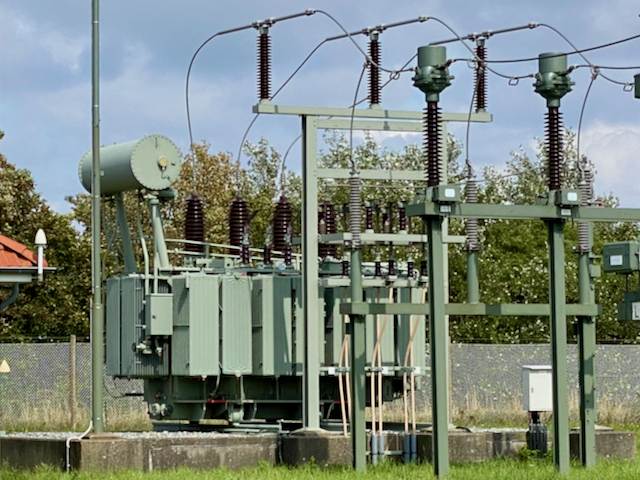
High-voltage transformer
The transformer stands in Keitum on Sylt. It transforms high voltage (110 kV), which arrives from the mainland via a submarine cable, to medium voltage (20 kV), which is then distributed across the island. In the picture from left to right: the expansion tank for the oil (conservator), the high-voltage connections with insulators (primary side), at the front (white) the medium-voltage cables (secondary side), on the outside sheet-metal stacks/radiators as part of the oil circuit for heat dissipation.
2 What can it do?
A transformer converts alternating voltages into other alternating voltages without establishing an electrical/galvanic connection between the primary and the secondary circuit. Transformers can fulfil the following functions:
- step voltages up or down (e.g. 400 V → 20 kV, 230 V → 12 V),
- ensure galvanic isolation between electric circuits (isolating transformer),
- match currents and voltages to the required load conditions (in the power supply).
3 How does it work?
The operating principle is based on electromagnetic induction:
- An alternating current flows through the primary coil and generates a time-varying magnetic field in the iron core.
- This magnetic field passes through the secondary coil, which is wound around the same iron core, and induces a voltage there.
- The turns ratio of the voltages results from the ratio of the numbers of turns.
4 What does it look like inside?
Inside you find:
- Iron core: mostly made of thin, stacked sheets (laminations) in order to reduce eddy currents and losses.
- Primary winding: copper wire, connected directly to the input voltage.
- Secondary winding: copper wire, supplies the output voltage.
- Insulation material: protects the windings from each other and from the core.
In power transformers, cooling (oil, fans) and protective mechanisms (Buchholz relay, temperature sensors) are added.
5 What role does it play in teaching?
The transformer is a central example of the law of induction and the interplay of magnetism and electricity. It illustrates how electrical energy can be transmitted over long distances with low losses (by means of high voltage) and is adapted for different applications (power supply). In the laboratory, students learn to trace the relationship between number of turns, voltage, current and power in practice. The isolating transformer reduces the risk of electrical accidents in the laboratory.
6 What role does it play in practice?
Transformers are indispensable in almost all areas of electrical engineering:
- Energy supply: high-voltage and distribution transformers for power grids.
- Supply of devices: mains transformers in chargers, audio amplifiers, household appliances.
- Signal transmission: small signal transformers in measurement and communication engineering.
- Safety: isolating transformers for galvanic isolation in laboratories and workshops.
Symbols
- Letter code in schematics: T
- Symbol: two coils with a common iron core (line or bar).
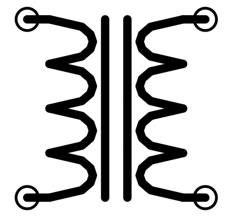
The marking at the terminals (small circle) is not standardized. Here it belongs to the representation in iCircuit.
Calculations
In the fundamentals of electrical engineering, no calculations are carried out for the transformer.
In alternating-voltage engineering, these calculations, among others, are then dealt with: