
Prof. Dr. Thorsten Jungmann (last updated 2026-03-02)
Review of the previous lesson
In the previous lesson, we dealt with the basic quantities and units of electrical engineering as well as important terms, symbols and models. The first quantities and formulas were introduced.
- You learned how to describe a simple electric circuit verbally and graphically, including naming the components and their functions.
- We dealt with the correct labelling of electrical quantities in schematics and represented the mathematical relationships between these quantities with formulas and graphs.
- In addition, we familiarized ourselves with the notation of electrical quantities, the rounding and precision of measured values and the use of units and orders of magnitude.
These basics form the foundation for our further study of electrical engineering.
Overview of this lesson
What is this lesson about? – The guiding questions:
- Where do the electric charges come from that build up the electric field, which in turn causes the current flow?
- How is electrical energy generated, stored and transmitted?
What will you be able to do at the end of this lesson? – The intended learning outcomes:
- You explain the principles by which electric voltage and current can be generated.
- You understand sources with their properties and functions.
- You know the relationships and differences between ideal and real current/voltage sources and can use these models to calculate the technical properties of sources with simple networks connected to them.
- You can represent sources symbolically and categorize them on the basis of their technical properties and the model concepts.
- You can set up and calculate equivalent circuits for linear sources.
What will you know at the end of this lesson? – The building blocks of knowledge:
- Ideal and real sources with internal resistance
- Battery and rechargeable battery
- Generator and transformer (overview)
- Rectifier (overview)
- Power grid (overview)
- Power supply
How is the content organized? – The structure:
- Where does electrical energy come from?
- Sources
- Principles of energy generation
- Effects of electric current
- Ideal sources
- Real sources and equivalent circuits
1 Where does electrical energy come from?
The largest source of energy available to humanity is the sun. At a distance of 150 million kilometres, it delivers a power of about 385 yottawatts (). Of this enormous power, about half a billionth (), i.e. about 173 petawatts (), reaches the earth in the form of radiant energy, i.e. electromagnetic waves in a spectrum of different wavelengths – including infrared radiation, visible light, ultraviolet radiation, microwaves, etc.
The incoming power corresponds to about 10 000 times the global demand, which is around 23 terawatts (TW), 23 trillion watts (). A growing but considerably smaller share of this comes from renewable energy. At the end of 2023, the installed photovoltaic capacity worldwide was about 1.6 TW (IEA 2023).
Unfortunately, the sun usually does not shine when we need heating and light in our homes, especially at night. This is why storage technology is of great importance.
If we use solar energy to lift, for example, 1 000 000 litres of water by 100 metres, we increase the potential energy (gravitational potential energy) of the water. To do this, we need the appropriate infrastructure (pipes, storage basins, etc.) and the power of suitable pumps.
If we then let the water flow downhill again through pipes and turbines, the turbines convert the kinetic energy of the water into mechanical rotational energy, which drives generators that convert the mechanical energy into electrical energy (current and voltage).
This electrical energy is fed into a grid from which energy can be drawn again at another location in order to do work in loads and to produce light and heat. (Work and energy are two different words for the same physical quantity; we have already clarified that.)
In the example of the hydroelectric power station mentioned above, the generators are the source of the electrical energy. A voltage is induced in them, and an electric current flows depending on the power drawn (). The energy corresponds to the power drawn over time ()
2 Sources
In electrical engineering, a source (German: Quelle) is an active circuit element that feeds energy into an electric circuit. It converts another form of energy (e.g. chemical, mechanical, thermal or radiant energy) into electrical energy in order to supply other components (the load).
Examples of sources in practice:
Batteries
Detail page battery
Batteries are primary cells:
- Not rechargeable
- Chemical energy is converted irreversibly into electrical energy
- Examples: alkaline batteries, lithium batteries
- Typical voltages: (alkaline), (lithium)
- Higher voltages by series connection of several cells
Rechargeable batteries
Detail page rechargeable battery
Rechargeable batteries are secondary cells:
- Rechargeable by reversing the chemical reaction
- Examples: Li-ion, NiMH, lead gel
- Typical voltages: (Li-ion), (NiMH), (lead)
- Higher voltages by series connection of several cells
Generators
Detail page generator
Principle: conversion of mechanical energy into electrical energy by electromagnetic induction
- Power stations: steam, gas and water turbines
- Mobile applications: vehicle alternators, emergency generators
- Renewable energy: wind turbines
Simplification
At this point, we neglect the form of the generated voltage and which further electrical components are necessary to make the generated voltage technically usable. Most generators produce a sinusoidal alternating voltage, which is electronically rectified and stabilized for direct-voltage applications.
Transformers
Detail page transformer
Principle: voltage transformation by magnetic coupling
- Turns ratio determined by the number of turns
- Suitable for alternating voltage only
- Application: transmission of electricity, power supplies
Power supplies
Detail page power supply
Principle: conversion of the AC mains voltage into direct voltage
- Transformer for voltage adjustment
- Rectifier for AC/DC conversion
- Fixed voltage or setting of the desired voltage (laboratory power supply)
- Filtering and stabilization
Solar cells
Detail page solar cell
Principle: photoelectric effect in semiconductors
- Direct conversion of light energy into electrical energy
- Silicon-based cells are the most common
- Typical voltage: per cell
2.2 Ideal and real sources
Basically, there are two types of sources:
- Voltage sources (German: Spannungsquellen): Supply a specific electric voltage, regardless of the current drawn by the connected load.
- Current sources (German: Stromquellen): Supply a specific electric current, regardless of the electric voltage across the connected load.
In practice, there are no perfect sources. Therefore, the model distinguishes between ideal and real sources.
Ideal sources
Ideal sources are a theoretical concept that does not occur in practice. Nevertheless, as a model, it is of great importance in this script.
- Ideal voltage source (German: ideale Spannungsquelle): Supplies a constant voltage, regardless of how much current is drawn. Its internal resistance is zero.
- Ideal current source (German: ideale Stromquelle): Supplies a constant current, regardless of the voltage at its terminals. Its internal resistance is infinite.
Real sources
In practice, every source is a real source.
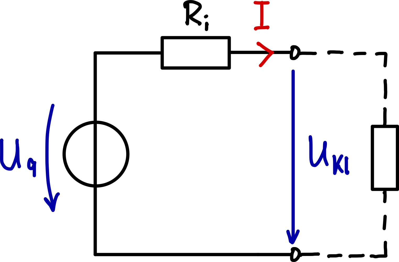
- Real voltage source (German: reale Spannungsquelle): Cannot keep its voltage completely constant. It is modelled by an ideal voltage source with an internal resistance connected in series. As the load (current) increases, the terminal voltage drops. Examples: power grid, battery and rechargeable battery.
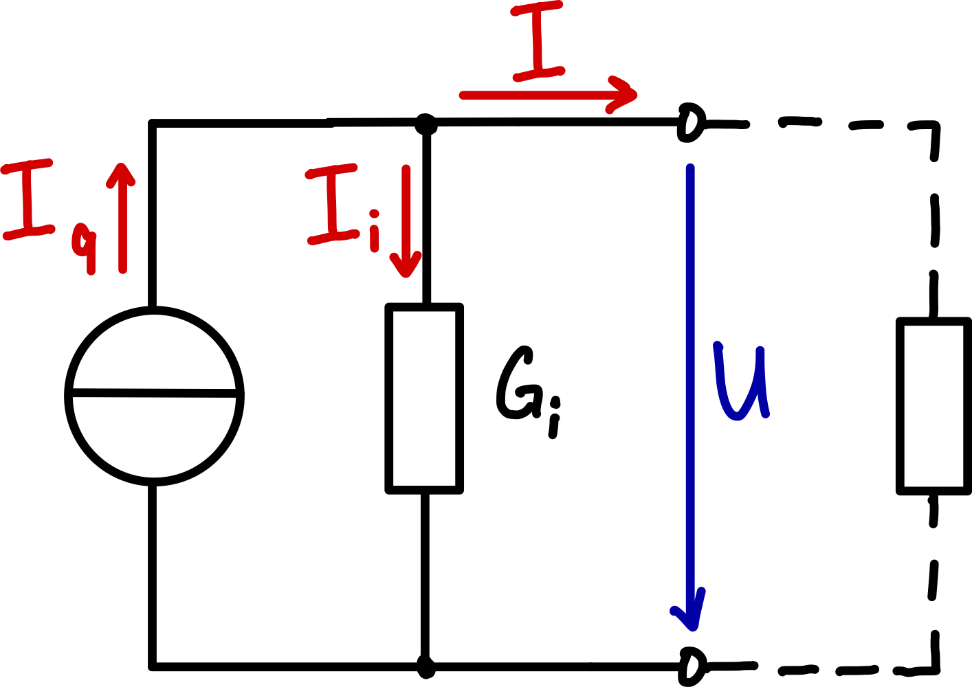
- Real current source (German: reale Stromquelle): Cannot keep its current completely constant. It is modelled by an ideal current source with an internal resistance connected in parallel. As the voltage increases, the current delivered to the load decreases. Examples: solar cell, charger.
2.3 Independent and dependent sources
In addition, sources are distinguished by their behaviour:
Independent sources
The output of the independent source is fixed and independent of other quantities in the electric circuit. Examples are batteries, which supply a fixed voltage, or laboratory power supplies. All sources that appear in this script belong to this group. Independent sources are single-port networks.
Dependent (controlled) sources
The output of the controlled source depends on another quantity (voltage or current) at another location in the electric circuit. Such sources are used in the analysis of semiconductor circuits, but they do not appear in this script.
3 Principles of energy generation
The various forms in which energy can exist are covered on the detail page on energy. They are:
- Mechanical energy
- Thermal energy
- Nuclear energy
- (Electromagnetic) radiant energy
- Chemical energy
The detail page also explains that the ‘generation’ of electrical energy, strictly speaking, means the conversion of one form of energy into electrical energy, since energy can be neither created nor destroyed. Thus the generator converts mechanical energy, the battery chemical energy and the solar cell light, i.e. electromagnetic radiant energy, into electrical energy. Exactly these three typical types of generation and the associated source characteristics appear in this script:
- Battery/rechargeable battery as an example of a real DC voltage source
- Solar cell as an example of a real DC current source
- Generator as an example of a real AC voltage source (not relevant for EE1)
Theoretical derivation
For the theoretical derivation of the most common source characteristics (generator, battery and solar cell), we start once again with Maxwell’s equations.
Generator
The electric field and the magnetic field are coupled by Faraday’s law of induction:
The induced electric field strength along a closed curve is obtained from the line integral:
For a moving wire loop in a magnetic field, the total voltage is:
Battery/rechargeable battery
Electrochemical voltage generation follows the Nernst equation, which links the chemical potential to the electric voltage:
where:
- the standard cell potential
- the universal gas constant ()
- the temperature in
- the number of transferred electrons
- the Faraday constant ()
- , the activities of the reduction and oxidation products respectively
Solar cell (illuminated diode)
I–U equation (single-diode model with series/shunt losses) (German: Ein-Dioden-Modell):
Special cases:
Short-circuit current ():
Open-circuit voltage ():
Maximum power point (MPP):
Photocurrent (spectral / practical) (German: Photostrom):
Diode (dark) current:
Quasi-Fermi levels / photovoltage (German: Quasi-Fermi-Niveaus / Photospannung):
Continuity (steady state) with generation and recombination (German: Rekombination):
with
Parameters and units:
- elementary charge , Boltzmann constant , temperature , emission factor
- currents
- voltages
- resistances
- cell area , irradiance
- photon flux density ,
- efficiency , fill factor
- mobilities , diffusion coefficients
- charge carrier densities
Note on the source characteristic (EE1 level) (German: Quellencharakteristik):
For , the following applies approximately:the solar cell then acts like a real DC current source (German: Gleichstromquelle).
In this script, the derivation serves purely academic purposes and is therefore not relevant for the examination in the sense that you do not have to reproduce it.
Charge separation
Electrical energy is produced by charge separation; positive charges are separated from the negative ones by expending energy.
The most important physical effects for charge separation are:
Electromagnetic induction (power station) (German: Induktion, Kraftwerk)
- Movement of a conductor in a magnetic field or change of the magnetic flux over time
- Application: generators, dynamos, transformers
Chemical effect (battery, rechargeable battery) (German: Batterie, Akku)
- Redox reactions at different electrodes
- Application: primary cells, secondary cells (rechargeable batteries)
Heat (thermocouple) (German: Thermoelement)
- Seebeck effect at different temperatures of different metals
- Application: temperature sensors, thermoelectric generators
Light (photovoltaics) (German: Photovoltaik)
- Photoelectric effect in semiconductors
- Application: solar cells, photodiodes
Pressure (piezoelectric crystal) (German: Piezo-Kristall)
- Mechanical deformation produces an electric voltage
- Application: piezo lighters, pressure sensors, ultrasonic transducers
Everyday example: LED torch
The LED torch with solar cell and dynamo combines various principles of charge separation: the solar cell uses the photoelectric effect, the crank dynamo the principle of electromagnetic induction, and the built-in rechargeable battery stores the separated charges electrochemically.
Separated charges in the source form an electric field, an imbalance that nature tries to compensate in order to restore equilibrium. The system strives for a state of minimum potential energy.
That is why the charges strive for equalization. This occurs when, in a closed electric circuit, charges (electrons) flow from the negative terminal of the source (anode, releases electrons) through conductive connections and, if applicable, a load to the positive terminal (cathode, accepts electrons). We speak of a steady current field when the current (like all other field quantities such as current density and the electric field) ‘settles’ at a value during operation and then flows steadily, i.e. constant in time.
Technical current direction
Although the electrons flow from minus to plus, the technical current direction is defined the other way round (from plus to minus). Voltage and current directions are assumed accordingly in the modelling and analysis of electric circuits: from the positive terminal of the source to the negative terminal.
4 Effects of electric current
As a result of the voltage at the terminals of the source, an electric current flows through the connected electric circuit. This current can cause various effects:
- Magnetic: electromagnets, electric motors, loudspeakers
- Chemical: electrolysis, electroplating, charging rechargeable batteries
- Heat: heaters, incandescent bulbs, soldering
- Light: light emitting diodes, fluorescent lamps, lasers
- Crystal deformation: piezo motors, ultrasonic transmitters
- Physiological effect: combination of chemistry and heat in living tissue
Important: electrical safety
If electrical devices are handled improperly, the physiological effect can lead to injury or even death.
The electric current results from the electric charge that passes through a conductor or resistor in a certain time:
How many electrons flow simultaneously through a cross-section of the conductor, relative to the area of this cross-section, is expressed by the current density. The current density is defined as the quotient of current and cross-sectional area:
5 Ideal sources
At this point, the discussion of ideal sources is taken further so that you can follow the concept with the help of worked examples.
5.1 Ideal voltage source
An ideal voltage source supplies a constant terminal voltage , regardless of the current flowing in the electric circuit. The terminal voltage is equal to the source voltage.
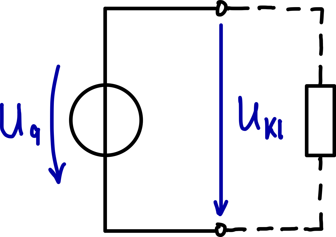
where:
- the voltage across the electric circuit in volts ()
- the source voltage in volts ()
The voltage is constant, regardless of the current that results from the connected load.
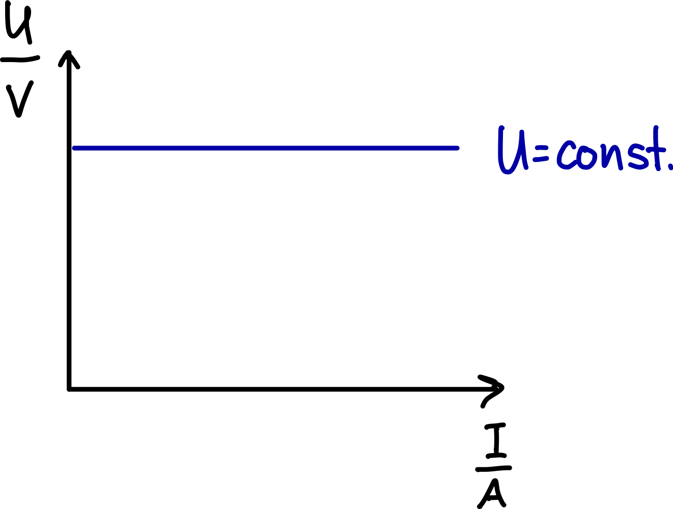
Example: Our power grid carries a constant (idealized).
5.2 Ideal current source
An ideal current source supplies a constant output current , regardless of the voltage across the connected electric circuit. The output current is equal to the source current.
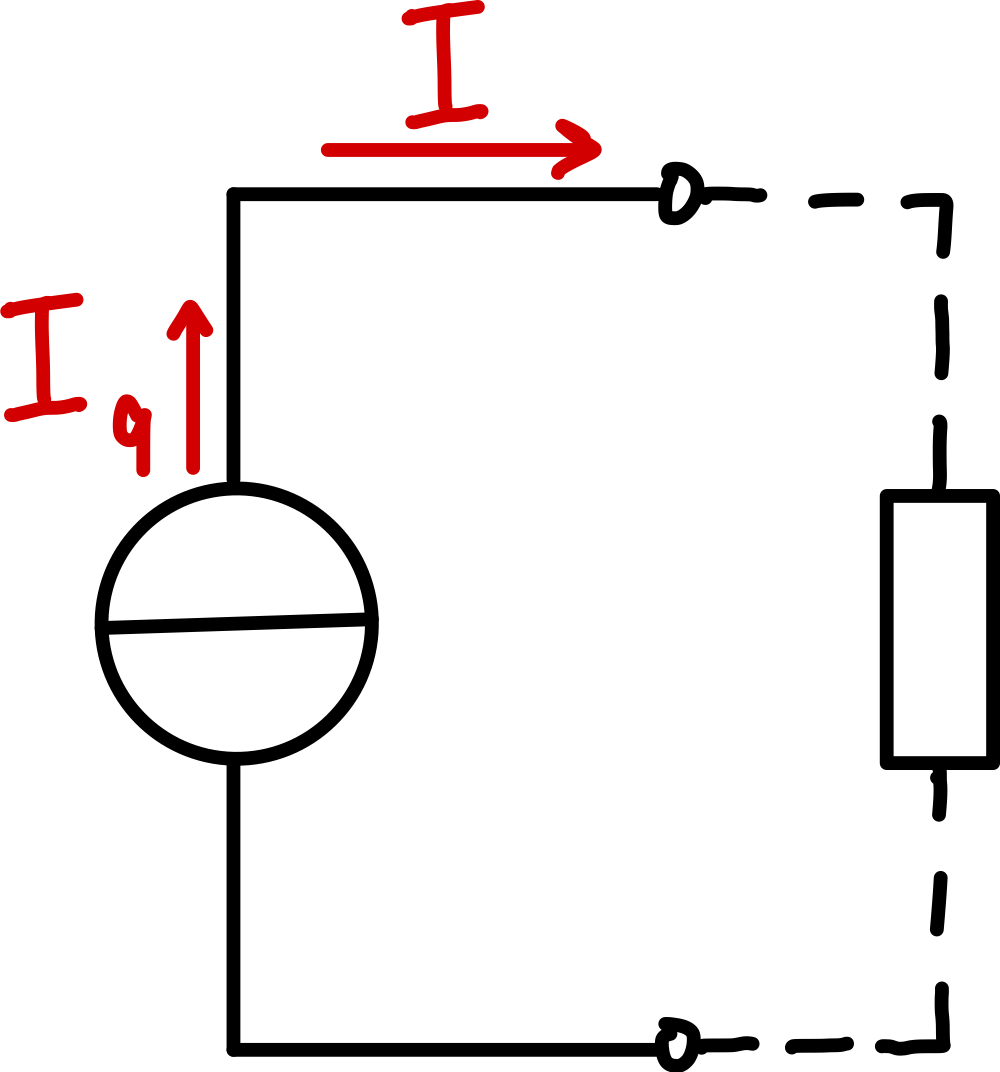
where:
- the current through the electric circuit in amperes ()
- the source current in amperes ()
The current is constant, regardless of the voltage that results from the connected load.
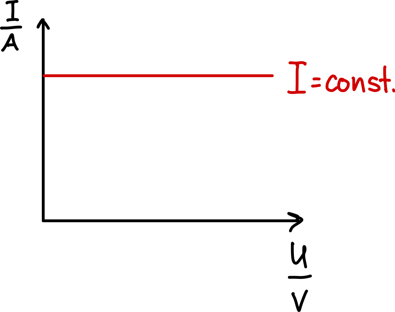
Example: A battery charger drives a constant charging current while the voltage across the rechargeable battery rises.
6 Real sources and equivalent circuits
A real source is a single-port network with two terminals that can deliver power to a load. The output power depends both on the properties of the source and on the connected electric circuit.
6.1 Properties of real sources
The real voltage source (German: reale Spannungsquelle) is modelled as an ideal voltage source with an internal resistance connected in series with the source.
The real current source (German: reale Stromquelle) is modelled as an ideal current source with an internal conductance connected in parallel with the source.
Two specific operating states characterize the real source in terms of electrical engineering:
Open circuit
In open circuit, the source is not connected to an electric circuit; nothing is connected to its terminals (). The open-circuit voltage can be measured between the terminals.
- Voltage source (German: Spannungsquelle): The open-circuit voltage equals the source voltage, since no voltage drops across the internal resistance ():
- Current source (German: Stromquelle): The open-circuit voltage results from the source current and the internal resistance, since the entire source current flows through :
Short circuit
In a short circuit, the terminals of the source are conductively connected to each other (). The short-circuit current flows between the terminals.
- Current source: The short-circuit current equals the source current, since no voltage drops across the internal resistance ():
- Voltage source: The short-circuit current results from the source voltage and the internal resistance:
6.2 Linear sources
The linear source is a special form of the real source. It has a linear current-voltage characteristic curve (I-U characteristic curve).
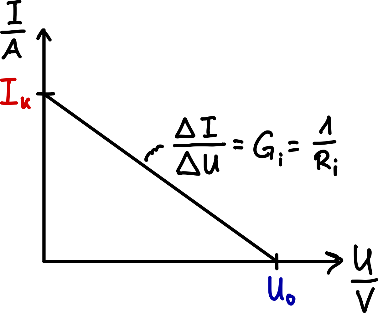
Its characteristic curve intersects:
- the ordinate ( axis) at at the point of the short-circuit current
- the abscissa ( axis) at at the point of the open-circuit voltage
Its characteristic curve can be described by:
and:
where:
- the constant internal resistance in ohms ()
- the constant internal conductance in siemens ();
In other words: the internal resistance or the internal conductance determines the (negative) slope of the straight line.
The sources that occur in the exercises for this script are linear sources.
Determining the operating point graphically
At the intersection of the source characteristic curve with the load characteristic curve, you can read off the steady-state operating point of a linear electric circuit.
6.3 Equivalent circuits for linear sources
The equations above are also the basis for modelling the linear source as an equivalent circuit and for calculating it. (→ EE1-07)
Linear voltage source with internal resistance in series:
Linear current source with internal conductance in parallel:
The two equivalent circuits are equivalent to each other; the following applies:
6.4 Practical example: battery tester
A battery is a real source.
A battery tester indicates the state of charge or the residual voltage of a battery. It helps you decide whether a battery can still be used or whether it is empty and has to be replaced. This takes more than just measuring the open-circuit voltage of the battery, e.g. with a multimeter.
A battery tester loads the battery with a load resistor of, for example, and then measures the terminal voltage, because:
- The open-circuit voltage of a source alone is not meaningful.
- An ‘empty’ battery often still has the correct open-circuit voltage, but a high internal resistance that does not become apparent in open circuit.
- Only under load does the internal resistance of the battery show itself. The terminal voltage of an empty battery then collapses, because a large part of the voltage drops across the high internal resistance.
Operating principle of a battery tester:
- Loading the source with a defined resistance
- Measuring the terminal voltage under load
Remember: as the battery ages and its charge decreases, its internal resistance rises.
6.5 Maximum power transfer
The internal resistance of a real source limits the power that the source can deliver. The maximum power is delivered when the load resistance is equal to the internal resistance:
In this case:
- The voltage is divided equally:
- The efficiency is only 50 % (the other half of the power is converted into heat in the internal resistance)
In practice, maximum power transfer is only aimed for when transferring the maximum power is more important than efficiency (e.g. in communications engineering).
For high efficiency, should apply.
Example: audio amplifier
Audio amplifiers are designed so that the maximum power reaches the loudspeaker (load resistor). The fact that audio signals involve impedance is not relevant here.
The principle is the same: the maximum power that the amplifier can deliver reaches the loudspeaker when the impedance of the amplifier matches that of the loudspeaker (usually or ).
⏭️ Continue with: EE1-04 Resistance 🔗
Exercises for this lesson
Exercise EE1-03.01 – Voltage drop across the internal resistance
Exercise EE1-03.02 – D cell
Exercise EE1-03.03 – Operating point of a source