
Prof. Dr. Thorsten Jungmann (last updated 2025-12-09)
Relates to EE1-03 Sources
Task
A radio transmitter for amateur radio operation has the following ratings:
- Maximum RF output power:
- Efficiency at maximum power:
- Rated supply voltage: (vehicle electrical system)
The transmitter is connected directly to a car battery via a cable of length with a cross-section of made of copper ().
Electrically, the transmitter behaves like an ideal resistor (simplified model).
a) What electrical input power does the transmitter need in rated operation?
b) What current does the transmitter draw in rated operation? Determine the input resistance of the transmitter.
c) Calculate the resistance of the connecting cable (outgoing and return conductors).
d) The car battery used has an open-circuit voltage of and an internal resistance of . Calculate the actual current and the actual voltage at the transmitter, taking all resistances into account.
e) What RF output power can the transmitter still deliver under these conditions?
f) Draw up the power balance under these conditions to check whether the power delivered by the source matches that of the loads.
Solution
a)
b) ;
c)
d) ;
e)
f)
Solution
Given
Given explicitly:
- RF output power (rated operation):
- Efficiency:
- Rated supply voltage:
- Cable length (one way):
- Cable cross-section:
- Resistivity of copper:
- Open-circuit voltage of the battery:
- Internal resistance of the battery:
Known:
- Efficiency:
- Power:
- Conductor resistance:
- Ohm’s law:
- Linear voltage source:
where:
- the efficiency (dimensionless)
- the RF output power in watts ()
- the electrical input power in watts ()
- the output power in watts ()
- the resistivity in
- the cable length in metres ()
- the cross-sectional area in square metres ()
- the internal resistance of the source in ohms ()
- the open-circuit voltage of the source in volts ()
- the terminal voltage in volts ()
Required
a) Input power in rated operation
b) Rated current and input resistance
c) Cable resistance
d) Actual current and terminal voltage
e) Actual RF output power
f) Complete power balance
a) Input power in rated operation
The transmitter converts electrical input power into RF output power with the efficiency :
b) Rated current and input resistance
At the rated supply voltage:
Since the transmitter behaves like an ideal resistor, the following applies:
Check using the power formula:
✔
c) Cable resistance
The cable consists of outgoing and return conductors, so the length is doubled:
The conductor resistance is calculated as follows:
d) Actual current and terminal voltage
Important consideration
The transmitter is a resistive load with a constant resistance . Together with the cable resistance and the internal resistance of the battery, it forms a voltage divider. The current is determined by the total resistance (German: Gesamtwiderstand) – not by the rated power!
Equivalent circuit diagram (German: Ersatzschaltbild):
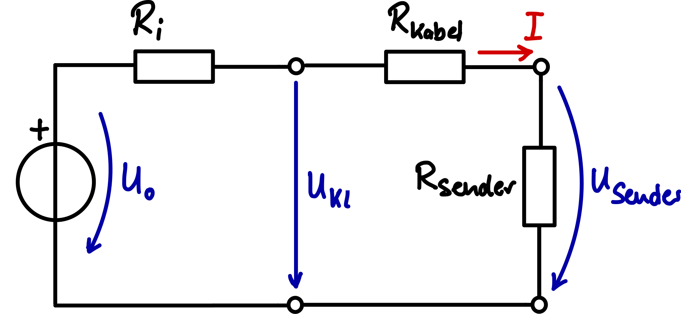
Total resistance in the electric circuit:
Actual current (Ohm’s law):
Terminal voltage at the transmitter:
Check using the voltage drop across the loss resistances:
✔
e) Actual RF output power
Electrical input power at the transmitter:
Or using the resistance:
✔
RF output power (German: HF-Ausgangsleistung):
Loss of power
The transmitter now delivers only 76 W instead of the nominal 100 W RF output power – a loss of 24 %!
This is due to:
- Lower open-circuit voltage of the battery ( instead of )
- Voltage drop across the internal resistance and the cable
Error analysis: What happens if we calculate with the previously determined rated current here?
An obvious but wrong approach would be: ‘The transmitter needs , so flow, and I use this to calculate the voltage drop.’
Incorrect calculation with the rated current :
Voltage drop across the loss resistances:
Terminal voltage at the transmitter (wrong):
Comparison with the correct values:
Quantity Correct Wrong (with ) Error Current Terminal voltage Transmitter power * *calculated with
Analysis of the error
Why is the voltage error small but the current error large?The voltage drop across is only approx. – whether we calculate with or changes this value by only . The voltage at the transmitter is therefore relatively robust against the current error.
But: The current itself is overestimated by almost ! And since the power is proportional to , this error propagates into all power calculations.
The fundamental error in reasoning:
The assumption ‘The transmitter always draws its rated current’ is wrong. A resistive load has a fixed resistance, not a fixed current draw. The current results from the interplay of source voltage and total resistance:
At a reduced supply voltage, the transmitter can no longer take up its rated power – it only takes up as much power as its resistance ‘allows’ at the applied voltage.
Practical relevance
In practice, many electronic devices do not behave purely resistively:
- Switch-mode power supplies (German: Schaltnetzteile) try to draw constant power (the current rises as the voltage falls)
- Linear regulators limit the current at undervoltage
- Electric motors (German: Motoren) change their resistance depending on the load
The resistive model is a simplification that is well suited to basic calculations. For precise analyses, the actual load behaviour must be taken into account.
f) Power balance
Power delivered by the battery:
Power loss at the internal resistance of the battery:
Power loss in the cable:
Power at the transmitter:
Check – power balance:
✔
| Component | Power | Share |
|---|---|---|
| Transmitter | ||
| Cable | ||
| Battery | ||
| Total |