
Prof. Dr. Thorsten Jungmann (last updated 2026-03-02)
Overview of this lesson
What is this lesson about? – The guiding questions:
- What conducts the current and what slows it down?
- How does Ohm’s law link voltage, current and resistance?
- How do conductor dimensions and material depend on the voltage drop?
- How do other physical quantities affect resistance?
- What to do with the voltage drop?
What will you be able to do at the end of this lesson? – The intended learning outcomes:
- You define electrical resistance,
- apply Ohm’s law confidently in the steady current field,
- calculate conductor, insulation and load resistances including voltage drop,
- take temperature-dependent changes into account and
- read off the operating point of an electric circuit with a resistor in the characteristic diagram.
What will you know at the end of this lesson? – The building blocks of knowledge:
- Resistance as a temperature-dependent quantity
- The resistor as a component
- Voltage drop
- Operating point of resistor and source in a closed electric circuit
How is the content organized? – The structure:
1 Definition of resistance
2 Conductor resistance
3 Voltage drop
4 Temperature dependence of resistance
5 The resistor as a component
6 Resistors in an electric circuit
1 Definition of resistance
We draw on the electrical quantities already introduced, first of all the voltage as the prerequisite for the flow of charge carriers, i.e. the electric current. We also draw on Ohm’s law, which has already been introduced, and now take a closer look at electrical resistance.
Electrical resistance describes the opposition to current flow in a component or conductor. Quantity symbol , unit ohm :
The following applies between voltage , current and resistance (for linear, ohmic behaviour):
Conductance is the reciprocal of resistance:
Wording
The resistor limits the current. A voltage drops across the resistor (voltage drop).
On the one hand, electrical resistance inevitably occurs in conductors as a consequence of their physical properties. On the other hand, there is also a component that bears the same name in German. In English, the difference is clear:
2 Conductor resistance
For a homogeneous, linear conductor, the following applies:
where:
- the conductor resistance, its conductance
- the resistivity of the conductor material, its conductivity
- the conductor length (take the outward and return path into account!)
- the conductor cross-section
2.1.1 Worked example
The winding of a generator consists of of copper wire with a cross-section of . The conductor resistance is:
Insulators
While conductors serve the technical purpose of conducting electric current, the task of insulators is to prevent current flow. For this purpose, they consist of materials with the highest possible resistivity or the lowest possible conductivity , e.g. PVC, glass or porcelain.
3 Voltage drop
According to Ohm’s law, a voltage drops across a conductor through which current flows. The voltage drop on an electric line of length is:
With :
You can find the material-dependent values of the resistivity on the detail page, e.g. for copper (Cu) or for aluminium (Al).
Standard in practice
In electrical installations, the permissible voltage drop from the point of supply to the load is limited by VDE 0100-520 to a maximum of of the rated voltage . In practice, is aimed for as a guide value.
From the equation you can see that, for a fixed length and constant current, the voltage drop decreases as the conductor cross-section increases ( is in the denominator). Accordingly, for long electric lines a larger cross-section is the solution for avoiding an impermissibly high voltage drop.
3.1.1 Worked example
The voltage drop across a 5 metre long, standard household extension lead made of copper (conductor cross-section ) through which a current of 5.0 A flows is:
The voltage drop on this electric line is:
It is therefore within the permissible limits.
Note
Of course, a proper, holistic analysis would also have to take into account the cable length up to the extension lead. For this worked example, however, this is not necessary.
4 Temperature dependence of resistance
Electrical resistance depends on temperature.
As the temperature increases, the atomic nuclei in the conductor material oscillate more strongly and thus form an increasing obstacle for the electrons flowing ‘between them’.
As the temperature decreases, the resistance of metals decreases steadily, since the thermal oscillation of the atomic nuclei subsides and the electrons are scattered less.
In some materials, below a material-specific transition temperature (German: Sprungtemperatur) , superconductivity (German: Supraleitung) sets in: the resistance drops abruptly to exactly zero.
For most superconducting elements, is close to absolute zero (e.g. niobium: ). Ceramic high-temperature superconductors reach transition temperatures of around , so that they can be cooled with liquid nitrogen (). However, many technically important metals such as copper, silver and gold do not become superconducting.
The resistance of most metals increases (approximately linearly within the limits to be assumed technically here) with the temperature difference :
where:
- the temperature coefficient, a material property that is specified for 20 °C, e.g. for copper:
Materials with a positive temperature coefficient (), whose resistance increases with rising temperature, are referred to as PTC thermistors (German: Kaltleiter) or PTC (Positive Temperature Coefficient). Most metals show PTC behaviour.
Materials with a negative temperature coefficient (), whose resistance decreases with rising temperature, are called NTC thermistors (German: Heißleiter) or NTC (Negative Temperature Coefficient). Typical NTC materials are semiconductors and special ceramics (e.g. thermistors).
4.1.1 Worked example
A copper electric line has a resistance of at 20 °C. If it heats up to 50 °C during operation, i.e. by , its resistance is:
If both resistances are given and the temperature is to be found, the formula rearranged for is useful:
Dependence of resistance on other physical quantities
Besides temperature, there are other physical quantities that can influence the resistance, e.g. strain, light, magnetic fields, electric fields, pressure/force, humidity and gas concentration.
Examples of technical applications:
The strain gauge (German: Dehnmessstreifen, DMS) is a resistive component whose resistance depends on its strain; it is used to measure bending and torsion, e.g. of beams and shafts.
The resistance of the photoresistor (LDR; German: Photowiderstand) decreases with increasing illumination; it is used to measure brightness, e.g. in light-sensitive switches.
The AMR resistor (German: AMR-Widerstand; anisotropic magnetoresistor) changes its value with the magnetic field passing through it; it is used, for example, for the contactless measurement of currents.
The varistor (German: Varistor) is a resistive component made of semiconductor material whose resistance decreases with increasing voltage; it serves to protect electrical components against overvoltage.In this script, however, only the temperature dependence of resistance is taken into account.
5 The resistor as a component
Besides resistance as a physical property of conductors and insulators, there is also the resistor as a component, which is manufactured with a defined resistance for the purpose of current limiting.
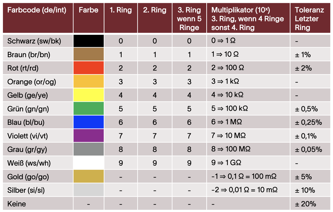
In addition to their rated value, real resistors also have a certain tolerance, power loss limits and temperature limits. Their characteristic values can usually be read from colour bands or printed digits.
You can read the characteristic values of resistors from the following table:
5.1.1 Reading example
A resistor with the colour bands ‘bn-gn-rd-gd’ has the value and can therefore have a value between and .
- brown: 1
- green: 5
- red: factor 100
- gold: tolerance +/- 5 %
6 Resistors in an electric circuit
6.1 Operating point
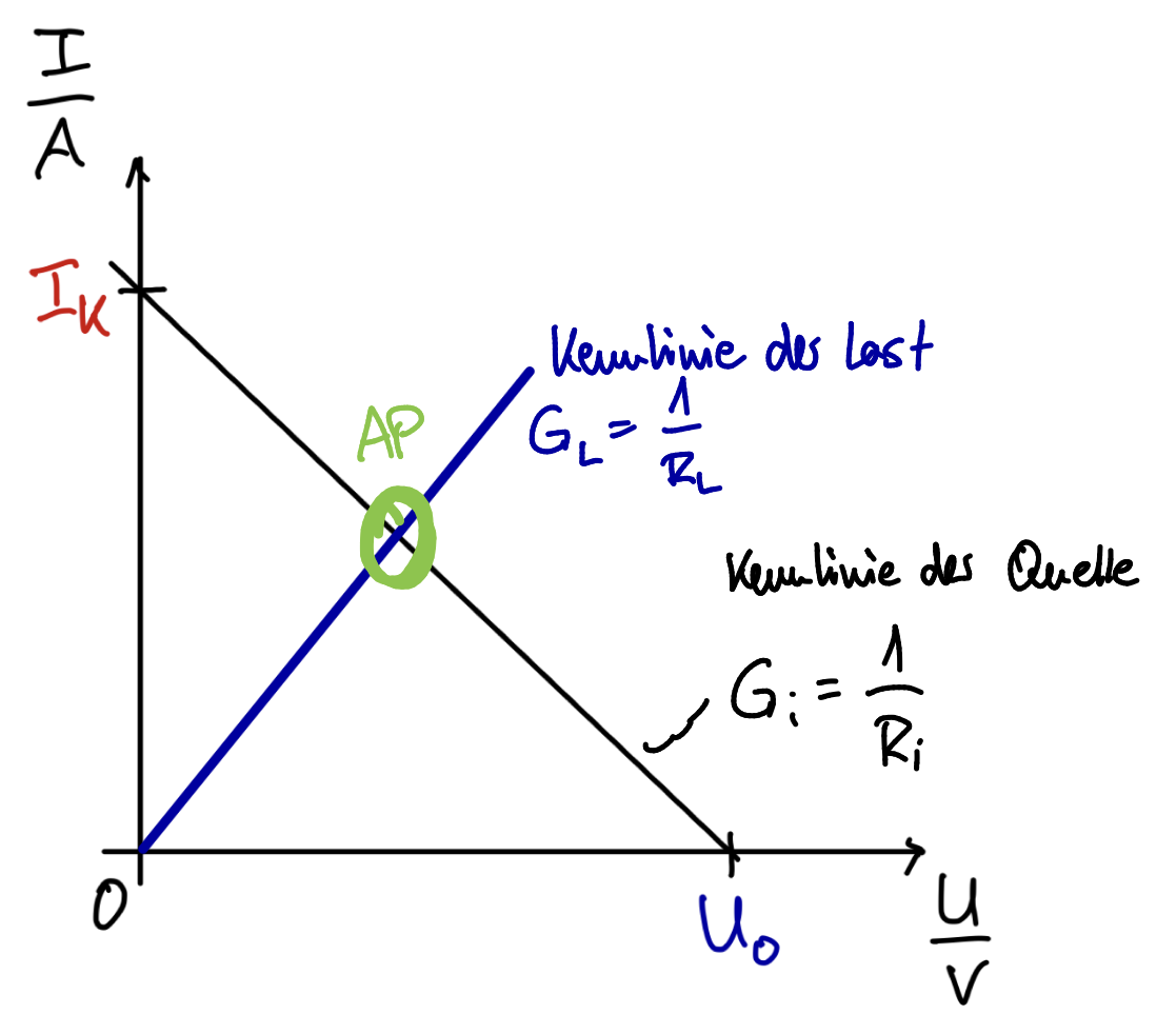
All resistors in this script are to be regarded as linear. If you now connect a linear source (with internal resistance) to a linear resistor, a steady state is established, i.e. all currents, voltages and resistances are constant over time.
Across the resistor , through which the current flows, the voltage drops.
The operating point (German: Arbeitspunkt) can be determined by calculation or read off at the intersection of the - characteristic curves of source and load.
6.1.1 Worked example: series resistor for a light emitting diode
A light emitting diode (LED) is to be operated at a voltage of 9.00 V, with a current of 20.0 mA flowing. Since the diode itself cannot limit the current, a series resistor is required to limit the current to the desired value. Without it, the diode would be destroyed as soon as it is switched on.
Given: , light emitting diode: at .
To find: .
Solution: From the E6 series you would select a resistor, from the E12 series a resistor.
6.2 Series connection of resistors
The total resistance of a series connection of resistors equals the sum of the individual resistances.
6.2.1 Worked example
Given:
Voltage divider
If a voltage is applied to a series connection of resistors, the voltages across the individual resistors are in the same ratio to the total voltage as the individual resistances are to the total resistance.
The same current flows through all resistors.
6.3 Parallel connection of resistors
The total conductance of a parallel connection of resistors equals the sum of the individual conductances.
Special case (n=2):
6.3.1 Worked examples
a) Three resistors in parallel
Given:
b) Special case
Given:
c) Special case: two identical resistors
Given:
Current divider
If a voltage is applied to a parallel connection of resistors, the currents through the individual resistors are in the same ratio to the total current as the individual conductances are to the total conductance.
The voltage is the same across all resistors of the parallel connection.For the special case of two resistors, this yields the equivalent cross rule (German: Kreuzregel), an inverse proportionality:
The larger current flows through the smaller resistor. Equivalently:
Reflection question
When is a large resistance ‘good’, and when is it ‘bad’?
Give one practical example of each.
Exercises for this lesson
Exercise EE1-04.01 – Determining resistance values
Exercise EE1-04.02 – Power of a resistor
Exercise EE1-04.03 – Temperature coefficient of an aluminium electric line
Exercise EE1-04.04 – Temperature coefficient measurement
Exercise EE1-04.05 – Conductor resistance and voltage drop of a cable reel
Classes from previous semesters
⏭️ Continue with: EE1-05 Equivalent resistance 🔗