
Prof. Dr. Thorsten Jungmann (last updated 2025-09-03)
1 What does it look like?
A resistor (German: Widerstand) is usually a small cylindrical or cuboid component with two terminals. Typical are the coloured bands on leaded carbon-film or metal-film resistors, which encode the resistance. SMD resistors (Surface Mounted Device) appear as small rectangular blocks with printed numbers. Wirewound resistors can be larger and embedded in ceramic housings in order to withstand higher powers.
Adjustable resistors (potentiometers) have an adjusting screw, a slider or a rotary knob and three terminals (start, end, wiper).
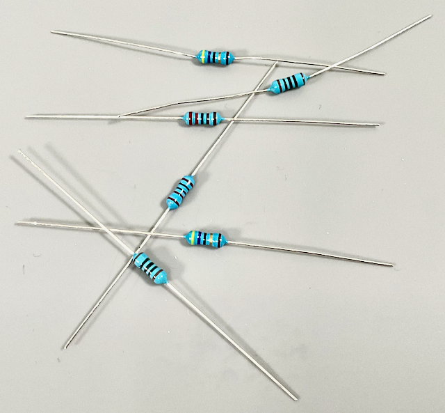
Resistors
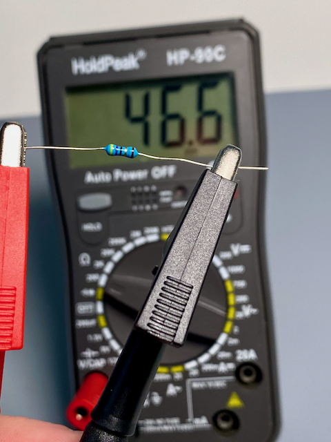
Resistance measurement with a multimeter
2 What can it do?
The resistor limits current, divides voltages (voltage divider), converts electrical energy into heat (heating resistor) and serves in electric circuits as a load, trimming or protective component. Resistors are basic elements in almost all electronic and electrical devices.
3 How does it work?
The resistor makes use of the electrical resistance of a material. The current flow is limited by the resistivity of the material.
- In carbon-film or metal-film resistors, a spiral is cut into a conductive film. This reduces the conductor cross-section and lengthens the current path.
- In wirewound resistors, a thin wire made of resistance material (e.g. constantan) is wound up. The long current path through the thin conductor cross-section limits the current flow.
- In SMD resistors, this effect is achieved by thin layers of conductive material on ceramic substrates.
- Across shunt resistors (shunts), a voltage drops that is proportional to the current according to Ohm’s law. In this way, currents can be measured without impeding the current flow.
4 What does it look like inside?
- Carbon-film and metal-film resistors: a carrier rod with a thin layer of conductive material applied to it, cut in a spiral to set the value, leads at the ends.
- Wirewound resistors: wound wire made of resistance material (e.g. constantan) on a ceramic body, often with a protective lacquer or housing.
- SMD resistors: a thin resistive film between two contact pads on a ceramic substrate.
- Strain gauges: a fine trace arranged in a meander pattern on a carrier, whose resistance changes measurably when it is stretched or compressed.
5 What role does it play in teaching?
The resistor is the simplest component in electrical engineering and the basis of many calculations. In teaching, it is used for Ohm’s law, for the relationship between voltage, current and power, and as an example of equivalent circuit diagrams. Resistors are also part of practically all laboratory set-ups.
6 What role does it play in practice?
Resistors are found in practically every electrical and electronic circuit: as current limiters (e.g. for light emitting diodes), as voltage dividers, as pull-up or pull-down resistors in digital circuits or as power resistors in drives.
Important in practice are:
- E series (German: E-Baureihen) (e.g. E6, E12, E24, …): Standard series for available resistances, graded according to percentage divisions of the decade.
- Tolerances (German: Toleranzen): Typical are ±20 % (E6), ±10 % (E12), ±5 % (E24) or ±1 % (E96). Modern precision resistors achieve up to ±0.1 %.
- Power rating (German: Belastbarkeit): Resistors are specified only up to a certain power loss (e.g. 0.25 W for small leaded types). Exceeding it leads to overheating and failure.
- Functional resistors (German: Funktionswiderstände): These include strain gauges, which change their resistance under mechanical deformation. They are used in measurement technology to detect forces, pressures or strains and are widely used in mechanical engineering, in automotive engineering and in scales.
Colour table
Using the colour bands applied to them, you can read the characteristic values of resistors from the table.
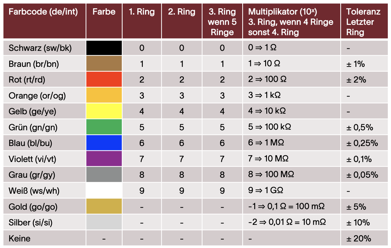
E series
Notation:
| Series | typical tolerance | normalized values (1.0–9.1) |
|---|---|---|
| E6 | ±20 % | 1.0 · 1.5 · 2.2 · 3.3 · 4.7 · 6.8 |
| E12 | ±10 % | 1.0 · 1.2 · 1.5 · 1.8 · 2.2 · 2.7 · 3.3 · 3.9 · 4.7 · 5.6 · 6.8 · 8.2 |
| E24 | ±5 % | 1.0 · 1.1 · 1.2 · 1.3 · 1.5 · 1.6 · 1.8 · 2.0 · 2.2 · 2.4 · 2.7 · 3.0 · 3.3 · 3.6 · 3.9 · 4.3 · 4.7 · 5.1 · 5.6 · 6.2 · 6.8 · 7.5 · 8.2 · 9.1 |
| Example: |
Symbols
- Letter code in schematics: R
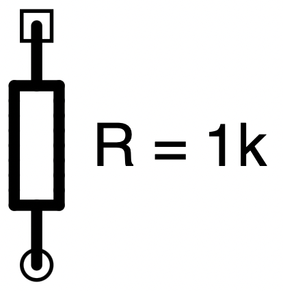
The marking at the terminals (circle and square) and the representation of the resistance are not standardized. Here they belong to the representation in iCircuit.
Calculations
- Ohm’s law
- Series and parallel connection
- Power loss