a) Describe the characteristics of analogue and digital signals, and name the differences between them.
b) Give three examples each of analogue and of digital signals, both from your private everyday life and from industry – twelve examples in all.
c) Explain in your own words what an analogue-to-digital (A/D) converter does in the signal chain from a sensor to an actuator, for example in the smartphone.
d) Explain in your own words what a digital-to-analogue (D/A) converter does in this signal chain.
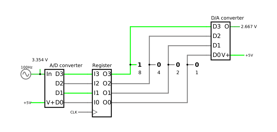
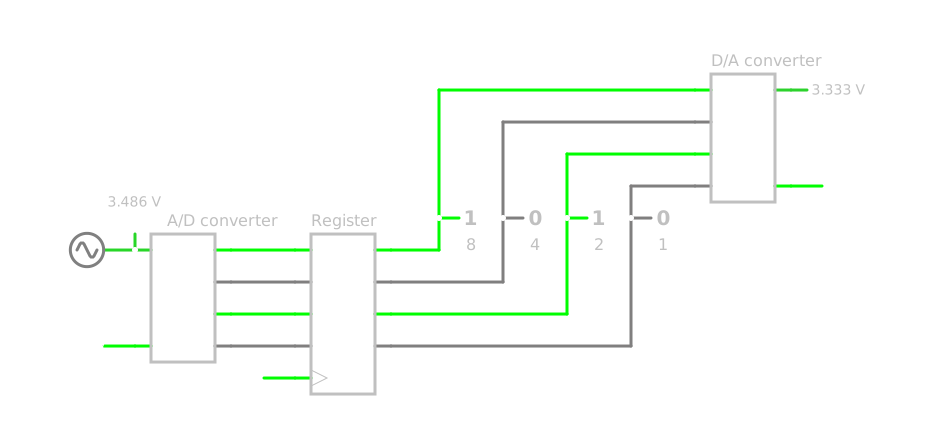
e) The simulation below converts a sinusoidal voltage of 100 Hz between 0 and 5 V into numbers with an A/D converter of 4 bits and turns them back into a voltage with a D/A converter of 4 bits. Each time the clock CLK of 2 kHz switches from 0 to 1, the register loads the number from the A/D converter and holds it until the next time; the four bits of this number appear above the weights 8, 4, 2 and 1. Open the simulation and compare the input voltage with the output voltage on the oscilloscope. Describe the difference, and explain where the steps of the output voltage come from. Think about how many different numbers 4 bits can represent and about what the register does.
f) Open the settings of the clock CLK in the simulation with a double-click and reduce its frequency, first to 500 Hz and then to 150 Hz. Describe what you observe on the oscilloscope. What follows for how often a converter has to take a number from its input?
Simulation: sinusoidal voltage of 100 Hz between 0 and 5 V; A/D converter and D/A converter with 4 bits each and a reference voltage of 5 V; register, loaded by the clock CLK of 2 kHz
Clock frequencies for f): 500 Hz and 150 Hz
Known:
Analogue and digital signals (DET-01); noise immunity and quantization error (DET-01)
Signal chain from sensor to actuator: the A/D converter turns a voltage into a number, the D/A converter turns a number back into a voltage (DET-01)
Required
a) The characteristics of analogue and digital signals and the differences between them
b) Three examples each of analogue and of digital signals, from private everyday life and from industry
c) The task of the A/D converter in the signal chain
d) The task of the D/A converter in the signal chain
e) The difference between the input and the output voltage in the simulation and the origin of the steps
f) The observations at 500 Hz and 150 Hz and what follows from them
a) Characteristics of analogue and digital signals
An analogue signal maps the information directly: its value – usually a voltage – follows the physical quantity, just as the voltage of a microphone follows the sound pressure. It changes continuously over time and can take any value within its range. Every disturbance that adds to the voltage on its way therefore becomes part of the information.
A digital signal carries the information in encoded form. It takes only discrete values, in the binary case the two values 0 and 1. Each of them is assigned a range of the voltage, and between the ranges lies a gap, which the signal passes through only while it switches. As long as a disturbance does not push the voltage out of its range, a 0 remains a 0 and a 1 remains a 1: this is the noise immunity of digital signals. A signal that an A/D converter has digitized is a sequence of numbers, taken at regular intervals.
Characteristic
Analogue signal
Digital signal
Values
any value within its range
only discrete values, in binary 0 and 1, each in its own voltage range
Information
mapped directly by the value
encoded, for example as a binary number
Course over time
changes continuously
jumps between its values; after A/D conversion, a sequence of numbers taken at regular intervals
Disturbances
become part of the information
change nothing as long as the voltage stays within its range
b) Examples of analogue and digital signals
Private everyday life – analogue signals:
The voltage of the microphone in the smartphone, which follows the sound pressure of your voice
The voltage at the loudspeaker or in the earbuds, which they turn into sound
The voltage of the rechargeable battery of the smartphone, which falls as the battery discharges
Private everyday life – digital signals:
The signal of the power button of the smartphone: pressed or not pressed, i.e. one bit
The data on the cable when you copy photos from the smartphone to a laptop
The signals between the processor and the memory of the smartphone
Industry – analogue signals:
The signal of a temperature sensor, for example the sensor for the outside temperature of a heat pump
The signal of a pressure sensor that measures the pressure in a pipe
The voltage with which a controller sets the rotational frequency of a fan
Industry – digital signals:
The signal of a light barrier at the digital input of a programmable logic controller (PLC): a workpiece is there or not
The signal of a limit switch that reports whether a machine part has reached its end position
The signal with which the controller of a heat pump switches a relay: on or off
Other examples are correct as well, as long as the signal maps its information continuously (analogue) or takes only discrete values (digital).
c) The A/D converter in the signal chain
In the chain from a sensor to an actuator, the sensor first turns a physical quantity into a voltage – an analogue signal. The A/D converter turns this voltage into a number, i.e. into a binary number of 0s and 1s that a microcontroller can process. In the smartphone, the microphone turns your voice into a voltage, and an A/D converter turns it into numbers, which the processor compresses and transmits. In the heat pump, the controller digitizes the signals of its temperature sensors in the same way.
d) The D/A converter in the signal chain
The D/A converter does the reverse: it turns a number back into a voltage, which then drives an actuator. On the phone of the person you are calling, a D/A converter turns the numbers back into a voltage, which drives the loudspeaker. Not every actuator needs a D/A converter: a relay, with which the heat pump switches pumps and valves, is switched on or off by a single bit.
e) Input and output in the simulation
On the oscilloscope, the input voltage runs as a smooth sine wave, and the output voltage of the D/A converter follows it as a staircase. The steps have two causes:
Steps in height: With 4 bits, there are only 24=16 different numbers, from 0000 to 1111. The output can therefore take only 16 different voltages – in the simulator from 0 V for 0000 to 5 V for 1111, in 15 equal steps of 1/3 V – whereas the input takes every value between 0 and 5 V. The A/D converter of the simulator assigns each voltage to the number just below it, so that the output lies at most one step below the input at the moment the number is loaded. This difference is the quantization error.
Steps in time: The register loads a new number only each time the clock CLK switches from 0 to 1, i.e. every 0.5 ms, and holds it in between. During this time, the output stays constant, while the input moves on; this is why the staircase lags behind the input. Where consecutive numbers are the same, as near the peaks, several clock periods form one longer step.
The four bits above the weights 8, 4, 2 and 1 show the number that the register holds at that moment: the larger the number, the larger the output voltage.
Outlook to DET-11: the steps of the conversion
DET-11 treats A/D conversion in detail, with these technical terms: taking the value of the input at regular intervals is called sampling (German: Abtastung), keeping it constant holding (German: Halten), and assigning it to one of a limited number of levels quantization (German: Quantisierung); finally, the converter has to encode (German: codieren) the number of the level as a binary number. In the simulation, the register holds the finished number; a real A/D converter holds the voltage before it quantizes it.
f) Lower clock frequencies
500 Hz: The register now loads a number only every 2 ms, i.e. five times per period of the sine wave. Each number is held four times as long as before, and the staircase becomes much coarser. Nevertheless, it still rises and falls every 10 ms, following the input of 100 Hz.
150 Hz: Now the register loads a number only every 6.7 ms, i.e. not even twice per period of the input. The output no longer follows the input: it changes only every 6.7 ms and oscillates slowly, with a period of about 20 ms, i.e. about 50 Hz – an oscillation that the input does not contain at all.
What follows: A converter has to take a number from its input often enough, several times per period of the signal. If it takes the numbers too rarely, they no longer describe the signal, and the output shows something that the input does not contain.
Outlook to DET-11: the sampling theorem
How often is often enough is stated by the Nyquist–Shannon sampling theorem: more than twice as often as the highest frequency that the signal contains. For the sine wave of 100 Hz, this means more than 200 numbers per second: 2 kHz and 500 Hz fulfil it, 150 Hz does not.
Back to the original state
Reloading the page loads the simulation again with the clock of 2 kHz.