Prof. Dr. Thorsten Jungmann (last updated 2026-11-02)

Relates to DET-05 Codes, code converters and standard components

Task

The three circuits below are drawn according to the standard of the International Electrotechnical Commission (IEC), IEC 60617. In each of them, follow the select inputs to find out what the multiplexers and demultiplexers do, and then fill in the gaps in the truth table. In the symbols, the data inputs and outputs carry their numbers; the data input with the number is called below.

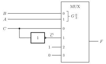
Circuit 1 has the inputs , and and the output .

Circuit 1 according to IEC 60617: a 4-to-1 multiplexer with the select inputs B and A and the data inputs C, C bar, 1 and 0, which drives the output F

a) Fill in the gaps.

RowSelected data input
00000
1001
20101
3011
4100
5101
61100
7111

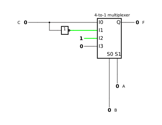
Check your truth table of a) in the simulation of circuit 1.

Simulation of circuit 1 with a 4-to-1 multiplexer, in which all inputs A, B and C are low and the output F is low

Open in the simulator

b) Give the minterm list of , and a disjunctive normal form (DNF) that follows directly from the data inputs.

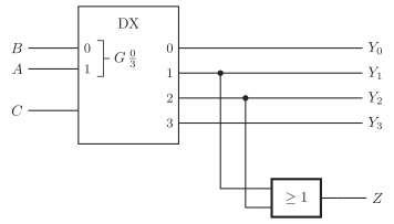
Circuit 2 has the inputs , and and the outputs to and .

Circuit 2 according to IEC 60617: a 1-to-4 demultiplexer with the select inputs B and A and the input C, the outputs Y0 to Y3, and an OR gate over Y1 and Y2 with the output Z

c) Fill in the gaps.

Row
000000000
100100
2010000
3011000
41000000
5101000
61100000
7111000

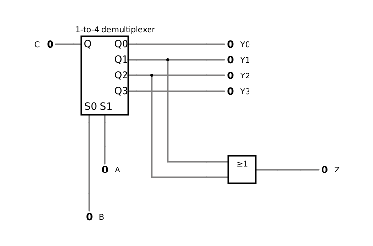
Check your truth table of c) in the simulation of circuit 2.

Simulation of circuit 2 with a 1-to-4 demultiplexer and an OR gate, in which all inputs are low and all outputs are low

Open in the simulator

d) Give the logic expression of . For which inputs is ? Say it in one sentence.

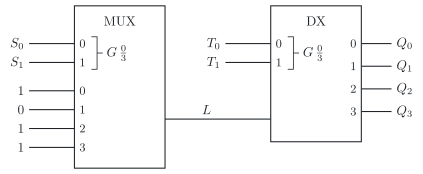
Circuit 3 sends four fixed data inputs over one line . It has the inputs , , and and the outputs and to .

Circuit 3 according to IEC 60617: a 4-to-1 multiplexer with the select inputs S0 and S1 and the data inputs 1, 0, 1 and 1 drives a single line L into a 1-to-4 demultiplexer with the select inputs T0 and T1 and four outputs

e) Fill in the gaps.

000011000
010100
10101000
1111000
001000
0100000
11011000
1011000

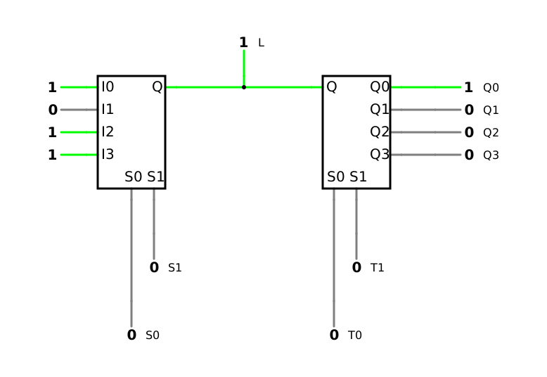
Check your truth table of e) in the simulation of circuit 3.

Simulation of circuit 3 with a 4-to-1 multiplexer and a 1-to-4 demultiplexer over one line, in which the select inputs are low and the line L and the output Q0 are high

Open in the simulator

f) Under which condition does each output show exactly its own data input , and what happens otherwise? How would you have to drive the select inputs for all four signals to share the line ?