Parts of the logic of a heat pump could be described in VHDL, for example for a programmable logic device. You do not need to write such code, but you should recognize it and sketch the circuit that it describes. Subtask a) is based on exercises in the textbook by LaMeres [5, p. 186], subtask e) on a concept check [5, p. 180].
Design 1 releases the compressor:
-- Release of the compressor of a heat pumpentity compressor_release is port (D, B : in bit; -- D: demand for heat, B: blocking signal of the energy supplier R : out bit); -- R: compressor releasedend entity;architecture behaviour of compressor_release isbegin R <= D and not B;end architecture;
a) Which part of design 1 describes the inputs and outputs, and which part describes the behaviour? Name each port with its direction and its type, and state the values that a port of type bit can take.
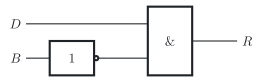
b) Sketch the circuit of design 1 according to the standard of the International Electrotechnical Commission (IEC), IEC 60617, and give its logic expression and its truth table.
Design 2 switches on a fault lamp:
-- Fault lamp of a heat pumpentity fault_lamp is port (C, P, Q : in bit; -- C: collective fault, P: command to switch the pump on, -- Q: feedback that the pump is running L : out bit); -- L: fault lamp onend entity;architecture behaviour of fault_lamp is signal X1 : bit; -- intermediate nodebegin L <= C or X1; X1 <= P xor Q;end architecture;
c) Sketch the circuit of design 2 according to IEC 60617, and give its logic expression and its truth table, with a column for the intermediate node X1. What does a 1 at X1 tell you about the pump?
d) Which of the following lines does VHDL accept? For each line that it does not accept, give the reason.
Line 1: Y <= A and B or C;
Line 2: Y <= (A and B) or C;
Line 3: Y <= A or B or C;
Line 4: Y <= A nor B nor C;
Line 5: Y <= not A and B;
e) In design 2, the output L is assigned before the intermediate node X1 that it uses. Does the circuit change if you swap the two assignments? Give the reason.
Design 1: entity compressor_release with the inputs D, demand for heat, and B, blocking signal of the energy supplier, and the output R, compressor released; assignment R <= D and not B;
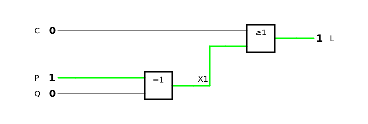
Design 2: entity fault_lamp with the inputs C, collective fault, P, command to switch the pump on, and Q, feedback that the pump is running, and the output L, fault lamp on; internal signal X1; assignments L <= C or X1; and X1 <= P xor Q;
d) five lines with signal assignments
Known:
Parts of a design in VHDL: the entity with its ports, each with name, direction and type, and the architecture with the behaviour; the type bit (DET-02)
One operator for each gate; only not takes precedence, all other logical operators have the same rank (DET-02)
From VHDL code to the circuit: each operator becomes a gate, each signal declared before begin an intermediate node; the assignments are concurrent (DET-02)
Schematic symbols according to the standard of the International Electrotechnical Commission (IEC), IEC 60617 (DET-02); XOR gate: 1 if its inputs differ (DET-02)
a) the part for the inputs and outputs, the part for the behaviour, the ports with direction and type, the values of bit
b) and c) the circuits, logic expressions and truth tables of designs 1 and 2; in c) also the meaning of X1
d) the lines that VHDL accepts, with the reason for each line that it does not accept
e) whether swapping the assignments changes the circuit
a) Parts of design 1
A design in VHDL has two parts (DET-02, 2.8). The entity compressor_release describes the interface: its port list names the inputs and outputs. The architecture behaviour describes the behaviour, here with a single signal assignment.
Port
Direction
Type
Meaning
D
in, input
bit
demand for heat
B
in, input
bit
blocking signal of the energy supplier
R
out, output
bit
compressor released
A port of type bit takes only the two values 0 and 1, written '0' and '1' in VHDL [5, p. 166].
b) Circuit of design 1
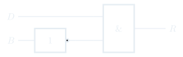
The operator not becomes an inverter for B, and and becomes an AND gate that combines D with the inverted B (DET-02, 6.4):
R=D⋅B
D
B
B
R=D⋅B
0
0
1
0
0
1
0
0
1
0
1
1
1
1
0
0
The compressor is released only in row 2, counting from row 0: there is a demand for heat, and the energy supplier does not block the operation.
Check with the precedence of VHDL: not acts only on B, so that D and not B means D⋅(B) and not D⋅B ✓
c) Circuit of design 2
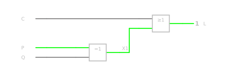
The architecture declares the signal X1 before begin: it is an intermediate node inside the circuit. The operator xor becomes an XOR gate for P and Q with the output X1, and or becomes an OR gate for C and X1 with the output L. The simulation shows the circuit:
The lamp is off only in rows 0 and 3: without a collective fault and with a pump that follows its command, whether it is switched off (row 0) or on (row 3).
X1 is 1 if command and feedback differ: either the pump runs although it should be off, or it should run but does not. A 1 at X1 therefore means that the pump does not follow its command; it is the inverted output of the XNOR gate that checks whether command and feedback agree (DET-02, 4.4).
Check of row 3 with the expression. For C=0, P=1 and Q=1:
L=C+(P⊕Q)=0+(1⊕1)=0+0=0
✓
In the simulation, you can switch the three inputs through all eight combinations and compare each result with a row of the table.
d) Lines that VHDL accepts
In VHDL, only not takes precedence; all other logical operators have the same rank. Without parentheses, an expression may therefore only chain the same operator, and nand and nor not even that (DET-02, 5.2):
Line
Code
Accepted
Reason or meaning
1
Y <= A and B or C;
no
mixes and and or without parentheses
2
Y <= (A and B) or C;
yes
Y=A⋅B+C
3
Y <= A or B or C;
yes
the same operator three times: Y=A+B+C
4
Y <= A nor B nor C;
no
nor cannot be chained
5
Y <= not A and B;
yes
not takes precedence: Y=A⋅B
Line 1 needs parentheses that state what is meant: (A and B) or C, as in line 2, or A and (B or C). Line 4 is rejected because NOR is not associative (DET-02, 5.4): the grouping changes the result. For A=1, B=0 and C=0:
A+B+CA+B+C=1+0+0=0+0=1=1+0+0=1+1=0
(A nor B) nor C gives 1, A nor (B nor C) gives 0.
Check with the examples of the lesson (DET-02, 5.2): there, too, Y <= A and B or C; and A nor B nor C are rejected for these reasons, and Y <= (A and B) or C; is correct ✓
e) Order of the assignments
No. The two assignments are concurrent: each of them describes a piece of hardware, here a gate, and both gates work at the same time (DET-02, 6.4). Unlike the lines of a program, they are not executed one after another. Whether L <= C or X1; stands before or after X1 <= P xor Q;, the XOR gate drives the node X1, and the OR gate combines it with C: the circuit and its truth table stay the same.
Why concurrency matters
In hardware, all gates work at the same time, as soon as they are supplied with power. A language that describes hardware must therefore describe things that happen in parallel [5, p. 180].