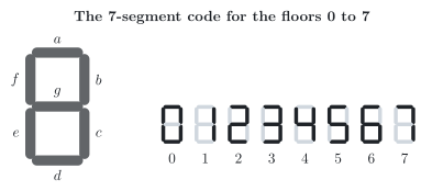
The cabin of a lift shows the floor on a 7-segment display. In a building with the floors 0 to 7, the controller of the lift delivers the floor as a binary code word with the bits A, B and C, A with the weight 4. A code converter turns this code word into the seven segment signals Ya to Yg; each of them is 1 when its segment lights up. The figure shows which segments form which digit, and the truth table gives the same code as bits.
Floor
A
B
C
Ya
Yb
Yc
Yd
Ye
Yf
Yg
0
0
0
0
1
1
1
1
1
1
0
1
0
0
1
0
1
1
0
0
0
0
2
0
1
0
1
1
0
1
1
0
1
3
0
1
1
1
1
1
1
0
0
1
4
1
0
0
0
1
1
0
0
1
1
5
1
0
1
1
0
1
1
0
1
1
6
1
1
0
1
0
1
1
1
1
1
7
1
1
1
1
1
1
0
0
0
0
a) Minimize Ya with a Karnaugh map.
b) Minimize Yd with a Karnaugh map.
c) Minimize Yg with a Karnaugh map. Is your result unique?
The other four segments are minimized in the same way, with these results:
Yb=A+B⋅C+B⋅C
Yc=A+B+C
Ye=A⋅C+B⋅C
Yf=A⋅B+A⋅C+B⋅C
d) Which product terms occur in the results of more than one segment? How many AND gates does the code converter need if it shares these terms between its segments, and how many if it does not?
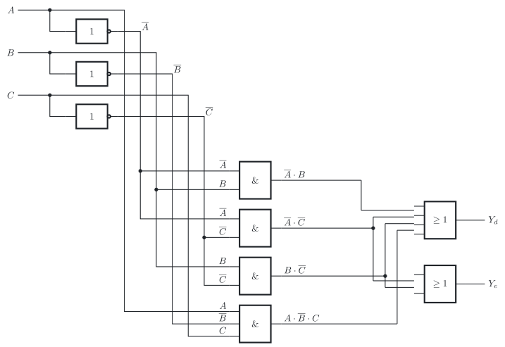
e) Draw the part of the circuit that forms Yd and Ye according to the standard of the International Electrotechnical Commission (IEC), IEC 60617, with shared AND gates.
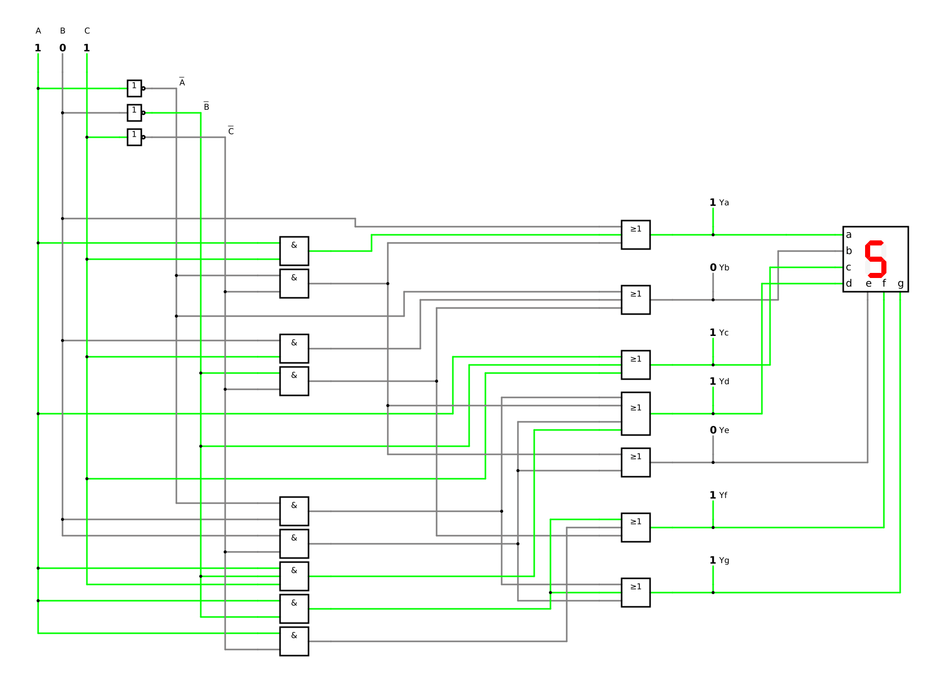
f) Check your results for floor 5: which segments light up, and does the digit agree with the truth table?
Karnaugh map with loops of ones (DET-03); minimizing the segments and sharing product terms between them (DET-05)
From the expression to the circuit (DET-03); checking the circuit against the description (DET-03)
Required
a) to c) the minimal disjunctive normal form (DNF) of Ya, Yd and Yg; in c) also whether it is unique
d) the product terms that several segments share, and the number of AND gates with and without sharing
e) the part of the circuit for Yd and Ye
f) the check for floor 5
a) Segment a
The truth table is already there: steps 1 and 2 of the synthesis are done (DET-03, 1.1). Steps 3 and 4 follow for each segment on its own, as for the 7-segment display decoder of the lesson (DET-05, 3.4). From the column Ya, read the floors with a 1:
Ya(A,B,C)=∑m(0,2,3,5,6,7)
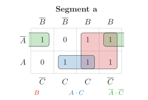
Put these ones into the map (figure) and draw the largest possible loops (DET-03, 4.2). The first and the last column are neighbours, so a loop may run across the edge.
The loops: B covers the floors 2, 3, 6 and 7, A⋅C covers the floors 5 and 7 and A⋅C, across the left and right edge, covers the floors 0 and 2:
Ya=B+A⋅C+A⋅C
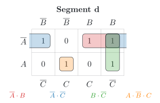
b) Segment d
The column Yd has a 1 on the floors 0, 2, 3, 5 and 6:
Yd(A,B,C)=∑m(0,2,3,5,6)
The loops: A⋅B covers the floors 2 and 3, A⋅C, across the left and right edge, covers the floors 0 and 2, B⋅C covers the floors 2 and 6 and A⋅B⋅C covers floor 5:
Yd=A⋅B+A⋅C+B⋅C+A⋅B⋅C
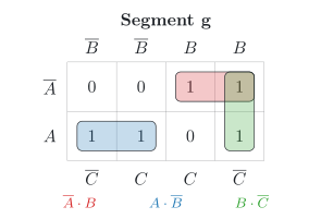
c) Segment g
The column Yg has a 1 on the floors 2, 3, 4, 5 and 6:
Yg(A,B,C)=∑m(2,3,4,5,6)
The loops: A⋅B covers the floors 2 and 3, A⋅B covers the floors 4 and 5 and B⋅C covers the floors 2 and 6:
Yg=A⋅B+A⋅B+B⋅C
The ones of the floors 3 and 5 each lie in only one loop, so A⋅B and A⋅B are essential. The one of floor 6 remains, and two loops of equal size can take it: B⋅C with floor 2 or A⋅C with floor 4. So the result is not unique. The other minimal DNF is:
Yg=A⋅B+A⋅B+A⋅C
The solution goes on with B⋅C, which Yd and Ye need as well.
The maps of the other four segments
The task gives these four results. Their maps show where they come from.
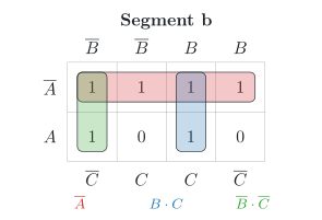
Segment b
The column Yb has a 1 on the floors 0, 1, 2, 3, 4 and 7:
Yb(A,B,C)=∑m(0,1,2,3,4,7)
The loops: A covers the floors 0, 1, 2 and 3, B⋅C covers the floors 3 and 7 and B⋅C covers the floors 0 and 4:
Yb=A+B⋅C+B⋅C
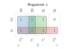
Segment c
The column Yc has a 1 on the floors 0, 1, 3, 4, 5, 6 and 7:
Yc(A,B,C)=∑m(0,1,3,4,5,6,7)
The loops: A covers the floors 4, 5, 6 and 7, B covers the floors 0, 1, 4 and 5 and C covers the floors 1, 3, 5 and 7:
Yc=A+B+C
This segment is dark on floor 2 only. Three single inputs need no AND gate at all.
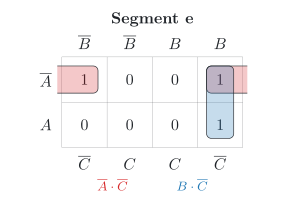
Segment e
The column Ye has a 1 on the floors 0, 2 and 6:
Ye(A,B,C)=∑m(0,2,6)
The loops: A⋅C, across the left and right edge, covers the floors 0 and 2 and B⋅C covers the floors 2 and 6:
Ye=A⋅C+B⋅C
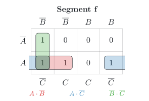
Segment f
The column Yf has a 1 on the floors 0, 4, 5 and 6:
Yf(A,B,C)=∑m(0,4,5,6)
The loops: A⋅B covers the floors 4 and 5, A⋅C, across the left and right edge, covers the floors 4 and 6 and B⋅C covers the floors 0 and 4:
Yf=A⋅B+A⋅C+B⋅C
d) Sharing product terms
A single input, such as B in Ya, needs no AND gate. The other product terms need one AND gate each, unless two segments use the same term; then one gate can serve both (DET-05, 3.4):
Product term
Used by the segments
Number of uses
A⋅C
a
1
A⋅C
a, d and e
3
B⋅C
b
1
B⋅C
b and f
2
A⋅B
d and g
2
B⋅C
d, e and g
3
A⋅B⋅C
d
1
A⋅B
f and g
2
A⋅C
f
1
The terms that occur in more than one segment are A⋅C, B⋅C, A⋅B, B⋅C and A⋅B. With shared terms, the code converter needs one AND gate for each row of the table, 9 in all. Without sharing, each segment builds its own terms. Segments a to g need:
2+2+0+4+2+3+3=16
So sharing saves 16−9=7 AND gates. With the other minimal form of Yg, both numbers stay the same: A⋅C exists anyway for Yf, and B⋅C for Yd and Ye. Only the list of shared terms grows: Yf and Yg then share A⋅C as well.
e) Circuit for two segments
Step 5 of the synthesis turns the expressions into gates (DET-03, 5.1). Yd needs an OR gate with four inputs over four AND gates. Ye needs an OR gate with two inputs and no AND gate of its own, because its terms A⋅C and B⋅C already exist for Yd (figure). The inverters for A, B and C serve all gates.
f) Check for floor 5
Step 6 compares the circuit with the description, here the truth table (DET-03, 5.3). Floor 5 is the code word 101. For A=1, B=0 and C=1:
The segments a, c, d, f and g light up. These are the ones in the row of floor 5 of the truth table, and in the figure they form the digit 5 ✓
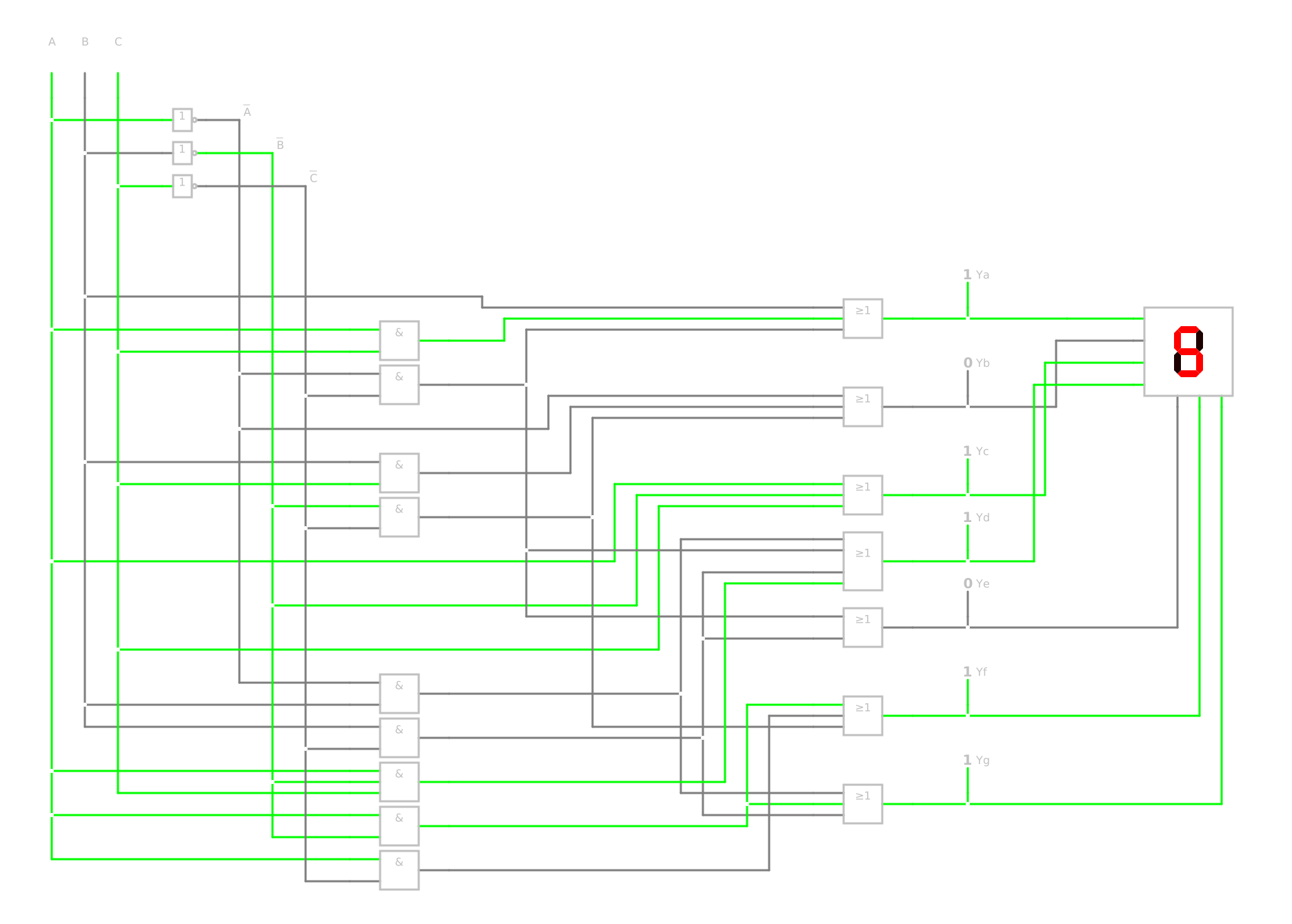
The simulation shows the whole code converter with its nine AND gates and seven OR gates (DET-05, 3.5). Switch the three inputs through all eight code words and compare the logic outputs and the digit with each row of the truth table.