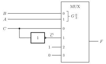
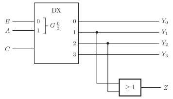
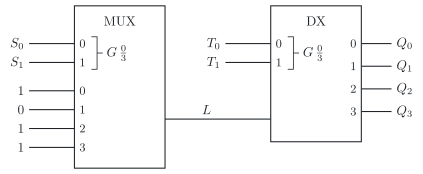
The three circuits below are drawn according to the standard of the International Electrotechnical Commission (IEC), IEC 60617. In each of them, follow the select inputs to find out what the multiplexers and demultiplexers do, and then fill in the gaps in the truth table. In the symbols, the data inputs and outputs carry their numbers; the data input with the number k is called Ik below.
Circuit 1 has the inputs A, B and C and the output F.
a) Fill in the gaps.
Row
A
B
C
Selected data input
F
0
0
0
0
I0
0
1
0
0
1
2
0
1
0
1
3
0
1
1
I1
4
1
0
0
5
1
0
1
I2
6
1
1
0
0
7
1
1
1
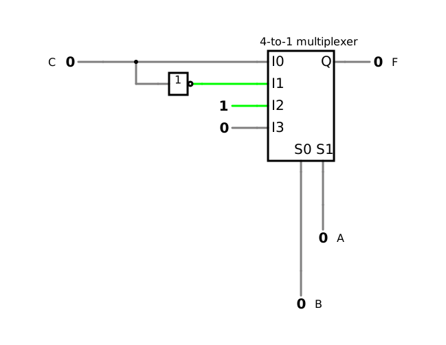
Check your truth table of a) in the simulation of circuit 1.
f) Under which condition does each output Qk show exactly its own data input Ik, and what happens otherwise? How would you have to drive the select inputs for all four signals to share the line L?
the three circuits with their inputs and outputs; in circuit 3 the data inputs 1, 0, 1 and 1
the truth tables with gaps
Known:
Multiplexer with n select inputs: it passes the data input whose number the select inputs form (DET-05)
Demultiplexer: it routes its input to the output whose number the select inputs form; the other outputs are 0; with its input at 1, it works as a decoder (DET-05)
Multiplexer as a function generator with 0, 1, C or C at the data inputs (DET-05)
Multiplexer and demultiplexer over a single line (DET-05)
Required
a), c) and e) the complete truth tables
b) the minterm list and a disjunctive normal form (DNF) of F
d) the expression of Z and when Z=1
f) the condition for correct transmission, and how all signals share the line
a) Circuit 1: truth table
A has the weight 2 and B the weight 1 (DET-05, 5.1), so they select I2A+B. In the rows with A=0 and B=0, the multiplexer passes I0=C; with A=0 and B=1, I1=C; with A=1 and B=0, I2=1; with A=1 and B=1, I3=0. So in row 1, with A=0, B=0 and C=1, it passes I0, and the output is 1.
Row
A
B
C
Selected data input
F
0
0
0
0
I0
0
1
0
0
1
I0
1
2
0
1
0
I1
1
3
0
1
1
I1
0
4
1
0
0
I2
1
5
1
0
1
I2
1
6
1
1
0
I3
0
7
1
1
1
I3
0
b) Circuit 1: minterm list and DNF
The output is 1 in the rows 1, 2, 4 and 5:
F(A,B,C)=∑m(1,2,4,5)
A DNF follows directly from the data inputs: each select combination contributes its data input (DET-05, 5.1, DET-05, 6.2). I0=C gives the term A⋅B⋅C, I1=C gives A⋅B⋅C, I2=1 gives A⋅B, and I3=0 gives nothing:
F=A⋅B⋅C+A⋅B⋅C+A⋅B
Check with row 5, with A=1, B=0 and C=1: the multiplexer passes I2=1, and the expression gives F=0+0+1⋅1=1 ✓
c) Circuit 2: truth table
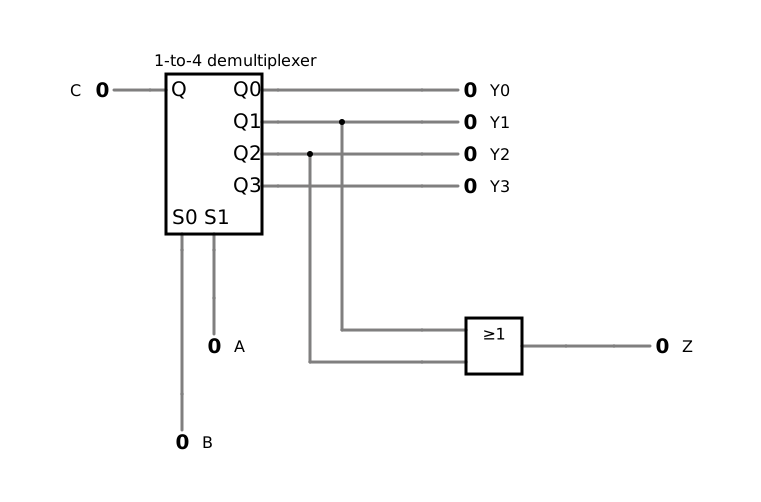
The demultiplexer routes C to the output Y2A+B, and the other outputs are 0 (DET-05, 5.2):
Y0Y1Y2Y3Z=A⋅B⋅C=A⋅B⋅C=A⋅B⋅C=A⋅B⋅C=Y1+Y2
Row
A
B
C
Y0
Y1
Y2
Y3
Z
0
0
0
0
0
0
0
0
0
1
0
0
1
1
0
0
0
0
2
0
1
0
0
0
0
0
0
3
0
1
1
0
1
0
0
1
4
1
0
0
0
0
0
0
0
5
1
0
1
0
0
1
0
1
6
1
1
0
0
0
0
0
0
7
1
1
1
0
0
0
1
0
For C=0, all outputs are 0, whichever output the select inputs choose.
d) Circuit 2: expression of Z
Y1Y2Z=A⋅B⋅C=A⋅B⋅C=Y1+Y2=A⋅B⋅C+A⋅B⋅C=(A⊕B)⋅C
Z is 1 if C is 1 and A and B differ: rows 3 and 5 of the table ✓
e) Circuit 3: truth table
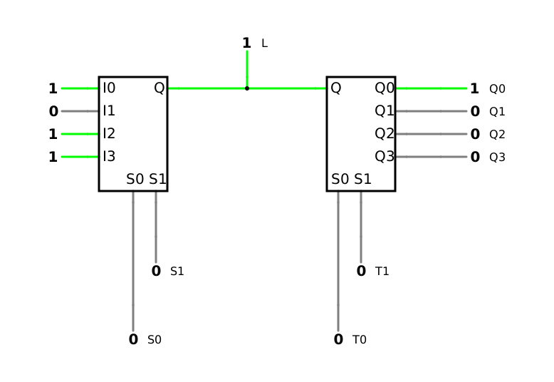
The multiplexer passes the data input that S1 and S0 select, so the line carries L=I2S1+S0. With the data inputs 1, 0, 1 and 1, this is 0 only for S1=0 and S0=1:
In the first four rows, S1 and S0 carry the same number as T1 and T0. There, Qk shows exactly its own data input: Q0=1, Q1=0, Q2=1 and Q3=1. In the other rows, the numbers differ, and the signal of one data input arrives at the output of another: in the row with S1=1, S0=1, T1=0 and T0=1, for example, I3=1 arrives at Q1, whose own data input is I1=0.
For all four signals to share the line, both pairs of select inputs have to run through the numbers 0 to 3 together, again and again. Each data input then gets its own time slot on the single line: time-division multiplexing (DET-05, 5.3).