The rotary encoder at a joint of a robot arm delivers the position of the joint in the Gray code, while the controller calculates in the binary code. The code disc has 16 sectors and four tracks. A code converter turns the Gray code word with the bits A, B, C and D into the binary code word with the bits Y3, Y2, Y1 and Y0, Y3 with the weight 8. This is the code table:
Sector
A
B
C
D
Y3
Y2
Y1
Y0
0
0
0
0
0
0
0
0
0
1
0
0
0
1
0
0
0
1
2
0
0
1
1
0
0
1
0
3
0
0
1
0
0
0
1
1
4
0
1
1
0
0
1
0
0
5
0
1
1
1
0
1
0
1
6
0
1
0
1
0
1
1
0
7
0
1
0
0
0
1
1
1
8
1
1
0
0
1
0
0
0
9
1
1
0
1
1
0
0
1
10
1
1
1
1
1
0
1
0
11
1
1
1
0
1
0
1
1
12
1
0
1
0
1
1
0
0
13
1
0
1
1
1
1
0
1
14
1
0
0
1
1
1
1
0
15
1
0
0
0
1
1
1
1
a) Minimize Y3 with a Karnaugh map.
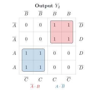
b) Minimize Y2 with a Karnaugh map.
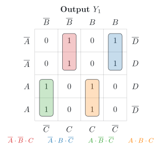
c) Minimize Y1 with a Karnaugh map.
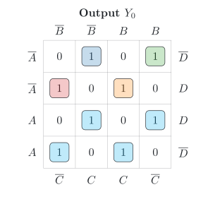
d) Draw the Karnaugh map of Y0. You do not need to write down its expression. What happens to the loops from a) to d)?
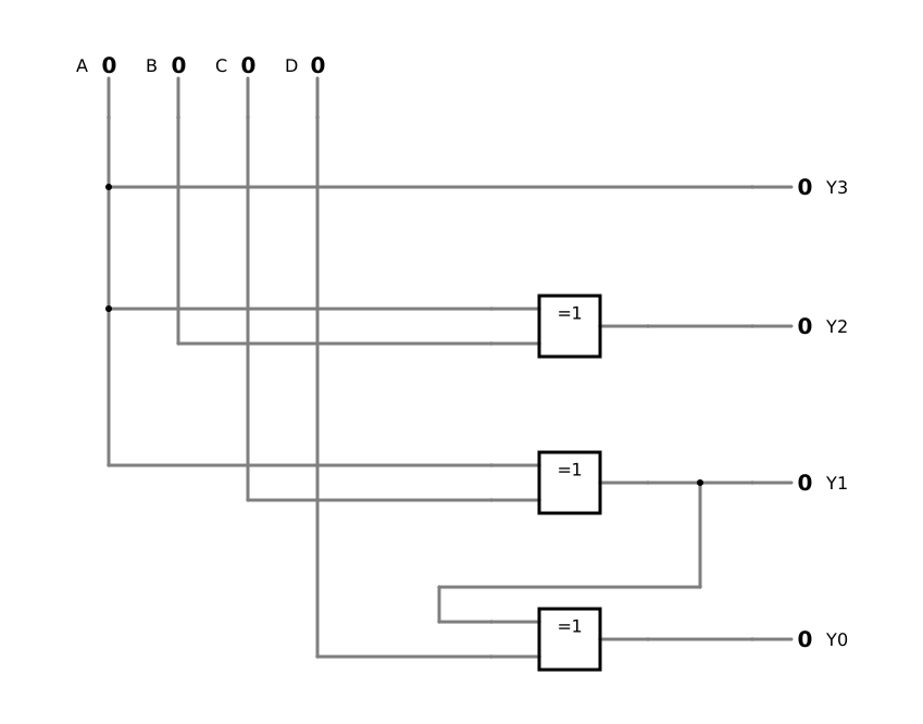
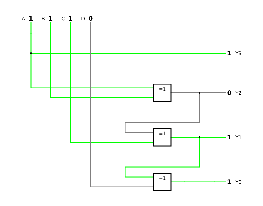
e) Express the four outputs with XOR gates with two inputs, as a chain from the highest bit down. How many XOR gates does the code converter need?
f) Check your chain for sector 11.
A colleague has built this code converter with a fault and reports: Y3 and Y2 agree with the code table in all 16 rows, but Y1 and Y0 do not:
g) In which rows do Y1 and Y0 deviate, and why do both outputs deviate in the same rows? Which input of which gate is connected wrongly? Confirm it in the simulation.
Code converter from Gray to binary as a chain of XOR gates (DET-05)
Karnaugh map with loops of ones and the chequerboard of the XOR operation (DET-03, DET-03)
Finding a built-in fault with the row-by-row comparison (DET-05)
Required
a) to c) the minimal disjunctive normal form (DNF) of Y3, Y2 and Y1
d) the map of Y0, and what happens to the loops
e) the chain of XOR gates and their number
f) the check for sector 11
g) the deviating rows, what they have in common and the wrong connection
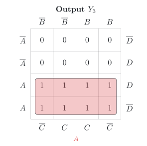
a) Output Y3
Steps 1 and 2 of the synthesis (DET-03, 1.1) are done with the code table. For steps 3 and 4, read the input code word of each sector with a 1 in the output. The cells of the map are numbered with the Gray code word as a binary number, A with the weight 8. The output Y3 is 1 for the sectors 8, 9, 10, 11, 12, 13, 14 and 15, whose code words all have A=1:
Y3(A,B,C,D)=∑m(8,9,10,11,12,13,14,15)
Y3=A
The eight ones form one loop, half of the map: a single input remains.
b) Output Y2
The output Y2 is 1 for the sectors 4, 5, 6, 7, 12, 13, 14 and 15. As binary numbers, their code words are:
Y2(A,B,C,D)=∑m(4,5,6,7,8,9,10,11)
Y2=A⋅B+A⋅B=A⊕B
Two loops of four remain. This form is the XOR operation of A and B (DET-02, 4.3).
c) Output Y1
The output Y1 is 1 for the sectors 2, 3, 6, 7, 10, 11, 14 and 15. As binary numbers, their code words are:
Y1(A,B,C,D)=∑m(2,3,4,5,8,9,14,15)
Y1=A⋅B⋅C+A⋅B⋅C+A⋅B⋅C+A⋅B⋅C=A⊕B⊕C
Only four loops of two remain, and no loop can be larger. The input D has dropped out, and the ones form a chequerboard in A, B and C (DET-03, 4.5).
d) Output Y0
The output Y0 is 1 for the odd sectors, 1, 3, 5, 7, 9, 11, 13 and 15. As binary numbers, their code words are:
Each 1 stands alone, because every neighbour of a cell with a 1 contains a 0: the map is a complete chequerboard, and the minimal DNF has eight terms with four literals each. No loop can minimize it; the XOR operation can (DET-03, 4.5).
From a) to d), every further input halves the size of the loops and doubles their number: 1, 2, 4 and 8 loops.
e) The chain of XOR gates
The results of a) to d) show the pattern: each output is the XOR of one more input. Each bit of the binary code word is the XOR of the Gray bit at its position and the binary bit above it (DET-05, 4.2):
Because each output needs the one above it, the XOR gates stand one behind the other, from the highest bit down. The code converter needs three XOR gates with two inputs. A two-level circuit would need eight AND gates with four inputs each and an OR gate with eight inputs for Y0 alone.
f) Check for sector 11
Sector 11 has the Gray code word 1110. For A=1, B=1, C=1 and D=0:
The binary code word is 1011. Check with the weights:
10112=8+2+1=11
✓
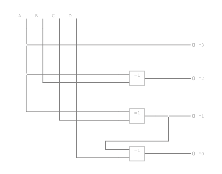
The simulation shows the chain; step 6 of the synthesis compares it with the code table (DET-03, 5.3). Switch the four inputs through the 16 code words, and compare the outputs with each row of the code table.
Step 6 compares each output with the code table, row by row (DET-05, 4.4). Y1 and Y0 deviate in the same rows, 4, 5, 6, 7, 12, 13, 14 and 15. These are exactly the rows with B=1. Y2 is correct, so look at the next gate in the chain: the XOR gate of Y1 should receive Y2 and C. Because Y2=A⊕B, the signals Y2 and A differ exactly where B=1. So this gate does not receive Y2 but A:
X1=A⊕C
Y0 is formed from this wrong signal, and an XOR gate passes a wrong input on as a wrong output, so both outputs deviate in the same rows. The first of them in the chain points to the fault: look at the gate of Y1, not at the gate of Y0.
The simulation confirms it: the upper input of the second XOR gate comes from A. To correct the fault, connect this input to Y2.